background image

6. SETTING AND ADJUSTMENTS BEFORE SHOOTING

44

VF

AUTO
WHITE

SKIN
AREA

ACCU
FOCUS

TAKE

VTR

PUSH

ZEBRA

AUDIO

LEVEL CH-1

ON

OFF

4.
5.

1.

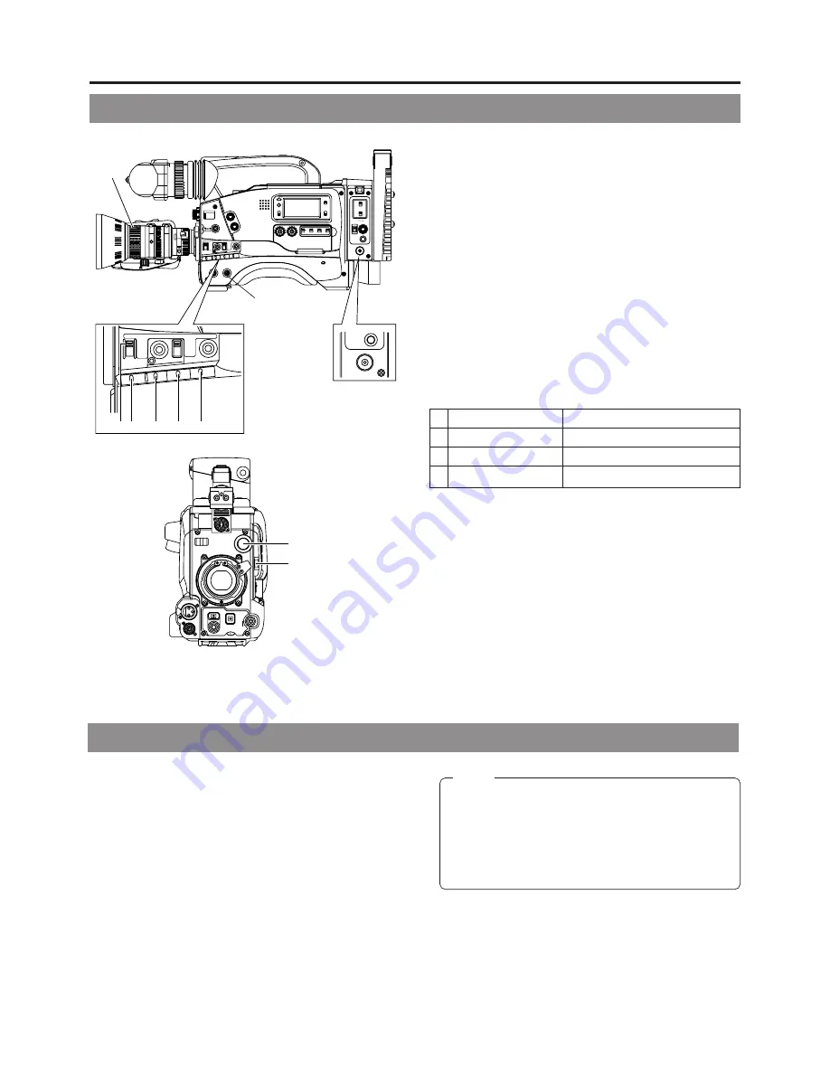
 POWER ON

1

 First place a charged battery pack in the battery case on

the rear section of the unit. If battery pack is not used,
connect DC power to the DC INPUT connector on the
rear section of the unit using the AC power adapter (AA-
P250) to supply DC 12 V current.

2

 Set the OPERATE switch on the unit to ON.

2.

 SWITCH positions

A.

Set the VTR switch to STBY.

B.

AUTO IRIS switch; set to NORMAL.

C.

GAIN switch; set to L. The L position is 0 dB.

D.

OUTPUT switch; set to CAM\AUTO KNEE OFF.

E.

WHT. BAL (Auto White Balance) switch; set to A or B.

3.

 Set the lens' iris mode switch to "A"  (AUTO IRIS side)

4.

 Choose the proper color temperature conversion filter.

5.

 Using the SHUTTER dial, set the shutter speed to OFF.

6-1 Camera Settings

FILTER

Suitable Location

1

3200K

Indoors, dark outdoors

2

5600K+1/8ND

Outdoors

3

5600K+1/64ND

Outdoors under clear sky

6-2 Screen Size (4:3/16:9 aspect ratio) Mode Selection

The screen size of recorded images can be selected in ASPECT
RATIO item of the Camera OPERATION menu screen. 

☞ 

See

page 79

To record using the standard screen, set ASPECT RATIO to
4:3.

When setting ASPECT RATIO to LETTER, images are
recorded on a screen of 16:9 aspect ratio split horizontally.
In this case, the viewfinder screen will show a 16:9 screen
that is horizontally split.

Memo:

• The safety zone of the standard screen or 16:9 screen

can be displayed on the viewfinder by setting SAFETY
ZONE item of the Camera VF DISPLAY menu screen.

☞ 

See page 78.

• When setting ASPECT RATIO to LETTER, 16:9

screen detection ID signal will not be outputted from
the Y/C OUT connector.

SHUTTER STATUS

MENU

FILTER

3200k

1

5600k+1/8ND

2

5600k+1/64ND

3

ALARM

MONITOR

OPERATE

NG

GAIN

OUTPUT WHT.BAL

VTR

ON

OFF

AUTO IRIS

LOLUX

BACK L

NORMAL
SPOT L

STRETCH

NORMAL
COMPRESS

LIGHT

ON

OFF

COUNTER

AUDIO SELECT

MANUAL

AUTO

CH-1

CH-2

CH-1

CH-2

REAR

FRONT

RM

AUDIO INPUT

MODE

CTL

TC
UB

CH-1

MIX

CH-2

RESET

OPERATE/WARNING

MONITOR 

SELECT

CH-1 AUDIO

LEVEL

CH-2

VTR

ON

OFF

INCOM

MIC

INCOM

MIC

LEVEL

POWER

OFF

RM

DC  IN
/BATT.

CALL

CARBON

DYNAMIC

FULL AUTO

BLACK

2.

3.

1.

GAIN

OUTPUT WHT.BAL

VTR

AUTO IRIS

LOLUX

BACK L

NORMAL
SPOT L

STRETCH

NORMAL
COMPRESS

FULL AUTO

BLACK

A

C

B

D

E

POWER

OFF

RM

DC  IN
/BATT.

CALL

1.

Содержание GY-DV550

Страница 1: ...odel No GY DV550 Serial No Thank you for purchasing this JVC product Before operating this unit please read the instructions carefully to ensure the best possible performance INTRODUCTION CONTROLS INDICATORS AND CONNECTORS BASIC SYSTEM CONNECTIONS AND ADJUSTMENTS POWER SUPPLY PREPARATIONS SETTING AND ADJUSTMENTS BEFORE SHOOTING SHOOTING OPERATION PLAYBACK MODE TIME CODE OPERATION S S F Super Scene...

Страница 2: ...utlet contact your electrician to replace your obsolete outlet Do not defeat the safety purpose of the grounding plug 11 For added protection for this product during a lightning storm or when it is left unattended and unused for long periods of time unplug it from the wall outlet and disconnect the antenna or cable system This will prevent damage to the product due to lightning and power line surg...

Страница 3: ...onsult the dealer or an experienced radio TV technician for help CAUTION CHANGES OR MODIFICATIONS NOT APPROVED BY JVC COULD VOID USER S AUTHORITY TO OPERATE THE EQUIPMENT INFORMATION FOR USA THIS DEVICE COMPLIES WITH PART 15 OF THE FCC RULES OPERATION IS SUBJECT TO THE FOLLOWING TWO CONDITIONS 1 THIS DEVICE MAY NOT CAUSE HARMFUL INTERFERENCE AND 2 THIS DEVICE MUST ACCEPT ANY INTERFERENCE RECEIVED ...

Страница 4: ...condition occurs in the unit Rec check function for convenient recording review Camera section designed with 3 CCD system for high quality picture Three 1 2 CCDs with 380 000 effective pixels employed Digital signal processing for reproduction of high quality picture Super sensitivity F 11 2000 lux Enables shooting at normal indoor illumination eliminating the need for extra illumination LOLUX for...

Страница 5: ...ding Operation 53 7 2 VCR Save Mode 55 7 3 If Unit is Left in Record Pause Standby Mode 55 7 4 Checking Recorded Contents in Record Pause Mode Recording Check Function 56 7 5 Recording External Video Signals 57 7 6 Recording with an External VCR 58 8 PLAYBACK MODE 8 1 Playback Procedure 60 8 2 Fast Forward Rewind 61 8 3 Search 61 BASIC OPERATIONS APPLICATION 9 TIME CODE OPERATION 9 1 Displaying Ti...

Страница 6: ... Switching 89 Gain Boost under LOLUX Condition 89 13 5 Switch Setup According to Illumination and Subject 90 Switch Functions 90 Full Auto Shooting FAS Function 90 13 6 How to Use Skin Tone Detail 91 13 7 Connecting the Local Remote Control Unit 93 13 8 Connecting the Camera Remote Control Unit 94 OTHERS STATUS SHUTTER MENU FILTER 3200k 1 5600k 1 8ND 2 5600k 1 64ND 3 ALARM MONITOR OPERATE NG GAIN ...

Страница 7: ...camera after use Protect the unit against penetration of dust when using it in a place subject to sandy dust Optical performance of lens Due to the optical performance of the lens color divergence phenomena magnification chromatic aberration may occur at the periphery of the image This is not a camera malfunction Noise may appear in the viewfinder when switching between the playback picture and th...

Страница 8: ...ng the RET button on the lens section RF appears on the display panel HEAD CLOG appears on the counter display VTR WARNING HEAD appears in the viewfinder If this kind of indication appears please stop the recording Head cleaning is required This indicator disappears when the OPERATE is turned OFF or when the cleaning tape is played back The GY DV550 incorporates precision mechanical parts which wi...

Страница 9: ...theless please be careful when shooting a bright light source Moire or Aliasing Shooting stripes or fine patterns may cause a jagged effect or a banding in fine mesh patterns White dots High temperatures can cause CCD sensor pixels to malfunction with the effect of white dots in the image This condition is conspicuous especially when gain is applied This is a characteristic of the charged coupled ...

Страница 10: ...ing color bar display The zebra patterns are not generated for the Y C OUT output See Zebra Pattern Display during ManualAdjustment on page 87 The default value is 70 80 The luminance level can be changed with the ZEBRA setting in the VF DISPLAY Menu screen See ZEBRA item on page 78 While this switch is pressed to the SKIN AREA side the color tone areas specified with the SKIN DTL ADJUST item on t...

Страница 11: ...e ring anticlockwise to release lens To mount lens make sure the lens guide pin fits well and then turn the ring clockwise until firm See Attaching the Zoom Lens on page 33 FILTER Color temperature conversion filter control knob This knob changes the internal color temperature filter See Camera Settings on page 44 2 1 Front Section Cont d As the automatic shutter is activated here flicker may appe...

Страница 12: ...ds or downwards to change the setting See How to Select from Camera Menu on page 77 5 LOLUX LOLUX On Off button This button toggles the LOLUX mode on and off LOLUX gain gives extremely low light level sensitivity for special applications This will result in an increase of 33 dB approximately 45 times in the LOLUX mode LOLUX operation takes priority over normal gain setting If the unit is placed in...

Страница 13: ...o Shooting FAS function on page 90 8 AUTO IRIS Auto iris level switch This switch selects the automatic iris adjustment reference value according to the condition in which the camera is used BACK L Under back light Opens the iris more than the standard level The level of iris can be set in SPOT L BACK L of the OPERATION MENU screen See page 79 NORMAL Normal condition SPOT L Under spotlight Closes ...

Страница 14: ...is switch is used to select the monitor sound output from the monitoring loudspeaker 1 or via the EARPHONE jack 2 on page 22 CH 1 The CH1 channel audio is output MIX CH1 and CH2 channel audio are output mixed CH 2 The CH2 channel audio is output 5 CH 1 AUDIO SELECT selector switch This switch is used to select the method for adjusting the audio input level of the CH 1 audio channel The reference a...

Страница 15: ...r user s bit will be preset in the time code generator In setup menu mode this button is used to confirm the menu item setting and save the data in the memory For details of the presetting of time code or user s bit see page 63 For details on the setup menus see page 73 CONTINUE button If this button is pressed simultaneously with the LOG button 8 on page 19 during the stop mode the tape winds to ...

Страница 16: ...llumination of the back lit display ON or OFF ON The display is illuminated OFF The display is not illuminated Keep this switch at OFF during battery operation of the GY DV550 or when it is required to reduce the power consumption for some reason 4 COUNTER switch Selects the contents displayed on the LCD counter display The displayed contents when TC or UB is set can be selected using the VCR Setu...

Страница 17: ...generator or the playback time code framing mode is non drop frame DF is displayed in the drop frame mode It never lights when the CTL counter is displayed HOLD indicator Lights when the time code generator display is held by pressing the HOLD button in the time code setting block The time code or user s bit can be preset while this indicator is lit See Displaying Time Code on page 62 Warning indi...

Страница 18: ... the user s bits should also be slave locked set the VCR Setup Menu item No 403 U BIT SLAVE to TC UB When the TC GENE switch on page 15 is set to REC or REGEN or the VCR Setup Menu item No 398 SSF MODE is set to CUEMODE or MARKMODE slave lockingwillnottakeplace For the slave lock of time code see page 64 5 TC OUT connector BNC Output connector for the LTC signal from the built in time code generat...

Страница 19: ...ly switches to the stop mode Tape protect mode The time until the tape protect mode is initiated can be set to 3 minutes or 30 minutes with the VCR Setup Menu item No 307 LONG PAUSE TIME When used in a cold environment the setting will be 3 minutes regardless of the setting on the VCR Setup Menu 6 REW button Press to rewind the tape Pressing the button in stop or fast forward mode initiates the re...

Страница 20: ...from the DC INPUT connector or the battery of this unit CARBON Use this setting when using a carbon type microphone DYNAMIC Use this setting when using a dynamic type microphone 6 MODE setting switch This switch is used to select the usage mode of the VTR RM multi pin connector RM This setting is used when connecting with the camera control unit VTR This setting is used when connecting and recordi...

Страница 21: ...ed to the AUX input connector of the camera remote control unit are outputted through VTR RM multi pin connector 8 Memo Camera images of this unit are recorded on the external VCR Compost video signals from GENLOCK AUX IN connector 8 on page 18 are not recorded When recording on an external VCR set the VTR INPUT switch 9 on page 15 to CAM and set the VTR SELECT switch to PARA or EXT Only CH1 audio...

Страница 22: ...pted when an earphone is connected here 3 DC OUTPUT connector Power output connector to a wireless microphone transmitter etc The supply voltage is identical to the voltage supplied to the unit DC 12V max 0 1 A 4 AUDIO IN REAR audio input rear connector XLR 3 pin Connect the external audio equipment or microphone to this connector Set the AUDIO IN REAR LINE MIC select switch 5 according to the con...

Страница 23: ...a control unit Enabled when the MODE switch 6 on page 20 is set to RM 8 DC INPUT connector XLR 4 pin Power input connector for 12 V DC Connect with the AA P250 optionalAC power adapter When a cable is connected here the power supply from the battery pack is interrupted and the source is switched to the power supplied through this connector When supplying power to the unit from this connector or ba...

Страница 24: ...um running time 4 Error code Alarm display The error code or alarm indicator is displayed automatically in case an abnormal condition occurs with the unit See TROUBLES WITH ERROR CODE OUTPUTS on page 100 See ALARM INDICATIONS on page 96 Remaining Battery Power Display The 7 dot segment bar display shows the remaining battery power The lighted segment bars decrease as the remaining battery power de...

Страница 25: ...IRIS speed adjusting control For adjusting the iris operation speed 0 FILTER thread Protect the lens with a clear filter or UV filter by screwing the filter onto the thread inside the lens hood from the front Other filters can be used for various effects ZOOM servo connector Connect an optional zoom servo unit here ZOOM mode knob S Servo zoom mode Allows operation by the zoom servo control lever 6...

Страница 26: ... to OFF to prevent the tally light 7 from turning on and informing people that they are being recorded However the REC indicator lamp in the eyepiece will not turn off 7 Tally light Lights when recording is in progress To prevent this light from coming on set the tally switch 6 to OFF 8 Eyepiece Ensures that ambient light does not reach the viewfinder screen or falls into the eye of the cameraman ...

Страница 27: ...ecording Blinks green Immediately before the tape is running out When an error occurs in the VCR 2 10 Indications in Viewfinder VIEWFINDER SCREEN DISPLAY The following indications are displayed on the viewfinder screen However this information is not displayed while the VCR section is playing back a tape Status screens screens for use in checking the current camera settings Alarm message display T...

Страница 28: ...he table below Status 0 2 10 Indications in Viewfinder Cont d q w e r t y u q w e r t u y i o 0 3 1 2 SCENE F I LE WH I TE BAL A A F I LTER SHUTTER 1 1 0 3 2K 0 0 GA I N 6 dB I R I S LEVEL NORMAL I R I S DETECT NORMAL FUL L AUTO OFF REC T I ME 6 0 ACCU FOCUS G F I B SD ACCU FOCUS G F I F5 6 STBY 4V 2 1 6 0 B CH1 CH2 SD M 9 0 9 5 4 REC2 EXT Status 0 Status 1 Status 2 Switch Event Display Contents Z...

Страница 29: ... video signal input or IEEE1394 input In the Super Scene Finder S S F mode the number of memorized scenes is shown M In MARK mode C In CUE mode Number Number of memorized scenes Displays whether the main unit is used for recording or the external VCR connected to the VTR RM multi pin connector The displays will differ depending on the VTR SELECT switch setting INT is constantly displayed during ex...

Страница 30: ...r VTR WARNING STOP Operation stopped VTR WARNING REW Rewinding abnormality TAPE NEAR END Remaining tape time is less than about 2 minutes in the record mode TAPE END Tape end reached 2 REC INHIBITAn unrecordable videocassette the switch on the back of the cassette is set to SAVE is inserted NO TAPE VTR trigger is pressed with no tape loaded Time Date Display When setting DISPLAY item of the TIME D...

Страница 31: ...e camera and VCR See Camera Menu Screen Flow on page 76 See VCR Setup Menu on page 72 This screen appears during the auto white balance adjustment operation to display various data See White Balance Adjustment on page 47 When the SHUTTER dial is pressed a shutter speed is displayed for approx 5 sec In addition whenever the shutter speed is altered by using the SHUTTER dial the shutter speed is dis...

Страница 32: ...H18 x 6 7K12 CANON TRIPOD 1 5 VIEW FINDER VF P115B VF P116 TRIMPAC HYTRON ANTON BAUER BATTERY HOLDER QRQ27 PRO PAC MAGNUM ANTON BAUER BATTERY IEEE1394 CABLE VX DV110 1m VX DV120 2m VX DV130 3m VX DV210 1m VX DV220 2m VX DV230 3m RS232C CABLE VC P893 PC AT Y C CABLE VCG30 VCG50 ANTON BAUER BATTERY CHARGER 4P 4P AC 3P GY DV550 STANDARD PACKAGE MACRO BNC CABLE 4P 4P 4P 6P STATUS SHUTTER MENU FILTER 3...

Страница 33: ... 3 Attaching the Viewfinder optional CAUTION 3 2 1 4 5 1 4 3 2 1 Loosen the stopper screw on the viewfinder 2 Connect the connector 3 Align the mounting guide with the camera s viewfinder mount base and attach the viewfinder 4 Tighten the stopper screw 5 Tighten the sliding securing ring To detach the viewfinder reverse the mounting procedure Hole Pin Mount ring When unplugging the cable connector...

Страница 34: ...ne holder with 2 screws 2 Turn the small knob located on the outer side of the microphone holder anticlockwise to loosen it and loosen the large knob located on the inner side in the same way Rotate the large knob fully anticlockwise to open the holder 3 Attach the microphone to the microphone holder so that the microphone does not interfere with the cassette cover 4 Set the microphone holder so t...

Страница 35: ... tripod before transporting it The tripod base KA 510 cannot be mounted 3 7 Attaching the 4 inch Viewfinder Optional CAUTION Use the optional viewfinder holder KA A40 to mount the 4 inch viewfinder VF P400 on the unit 1 Mount the viewfinder holder on the handle section of the unit Mount it so that the stopper pin of the viewfinder holder comes to face the front of the unit 2 Fix the viewfinder hol...

Страница 36: ...backup data STATUS SHUTTER MENU FILTER 3200k 1 5600k 1 8ND 2 5600k 1 64ND 3 ALARM MONITOR OPERATE NG GAIN OUTPUT WHT BAL VTR ON OFF AUTO IRIS LOLUX BACK L NORMAL SPOT L STRETCH NORMAL COMPRESS AUDIO SELECT MANUAL AUTO CH 1 CH 2 CH 1 CH 2 REAR FRONT RM AUDIO INPUT MODE CH 1 AUDIO LEVEL CH 2 VTR ON OFF INCOM MIC INCOM MIC LEVEL POWER OFF RM DC IN BATT CALL CARBON DYNAMIC FULL AUTO BLACK MENU OVER OV...

Страница 37: ...the video and audio signals occurs Audio signal are muted When operation is continued with DC input after the battery pack capacity has been used up set the OPERATE switch to OFF after the DC power is applied Then switch ON again If the GY DV550 is left with the battery pack attached a small amount of power is consumed even if the OPERATE switch on the GY DV550 is set to OFF Remove the battery pac...

Страница 38: ...ion Cont d 1 Open the battery case cover while pushing the lock release lever 2 Insert the battery pack into the battery case with its electrodes facing the unit 3 Close the battery case cover Lock release lever Be sure to set the POWER switch to OFF before replacing the battery pack ...

Страница 39: ...k 1 Align the 3 guide pins of the battery pack with the guide holes on the battery holder and push straight to insert the battery pack The battery cannot be attached properly if the guide pins are not inserted straight 2 Slide the battery pack toward the side panel where the cassette cover is located until it clicks Now the battery pack has been attached Detaching the Battery Pack While pushing an...

Страница 40: ...When the VF P115B is used as the viewfinder and a fully charged battery pack is attached the approximate continuous operating time is as follows Battery operating time may differ depending on the number of times the battery has been charged charging conditions and the operating environment etc Use the values in the table on the left for approximate reference times Operating time is reduced in area...

Страница 41: ...arts recording immediately 5 1 Turning the Power ON Wait at least 5 seconds before turning the OPERATE ON again once it has been turned OFF When the OPERATE is turned OFF the unit automatically enters the tape protect mode It takes approximately 5 seconds to enter the tape protect mode Do not turn the OPERATE ON again within this interval External VCR will not enter the SAVE mode Do not directly t...

Страница 42: ...e slot after removing the tape slack Ensure that the videocassette is fully inserted The cassette indicator on the display blinks during tape loading and lights steadily after the loading has been completed 4 Slowly close the cassette cover by pushing it in all the way When the cassette cover is closed the OPERATE LED lights up green and the unit is in the condition where it can be operated In the...

Страница 43: ... The date Month Day Year is indicated on the counter display 3 Press the HOLD button to enter the setting mode The HOLD indicator lights up on the display to indicate that the unit is in the setting mode The leftmost digit on the counter blinks 4 Set the date and time Each time the ADVANCE button is pressed the value of the blinking digit increases Each time the SHIFT button is pressed the digit t...

Страница 44: ...mages can be selected inASPECT RATIO item of the Camera OPERATION menu screen See page 79 To record using the standard screen set ASPECT RATIO to 4 3 When setting ASPECT RATIO to LETTER images are recorded on a screen of 16 9 aspect ratio split horizontally In this case the viewfinder screen will show a 16 9 screen that is horizontally split Memo The safety zone of the standard screen or 16 9 scre...

Страница 45: ... and brightness 1 Connect a color video monitor to the MONITOR OUT connector of the GY DV550 2 Set the OUTPUT switch to BARS to output the color bar signal SMTPE type color bars 3 Set the monitor s BLUE CHECK function to ON so that the screen turns entirely blue 4 Adjust the CHROMA control of the monitor so that there is no difference in brightness between the color bars 1 and 8 7 and D 5 With the...

Страница 46: ...nual 3 Open the iris ring If the illumination is too strong reduce it or move to a darker place 4 Turn the zoom lever until the lens is at the maximum telephoto position 5 Bring the subject into focus 6 Set the lens to maximum wide angle 7 Loosen the back focus ring retaining knob 8 View the same subject and adjust the back focus ring for the best possible focus 9 Repeat steps 4 through 8 about th...

Страница 47: ...or temperature conversion filter or use another white object and re adjust the white balance ERROR LOW LIGHT Insufficient illumination Displayed when the illumination is dim Increase the illumination and then re adjust the white balance ERROR OVER LIGHT Excessive illumination Displayed when the light is excessively bright Decrease the illumination and then re adjust the white balance FULL TIMEAUTO...

Страница 48: ...s Color video monitor Memo Color signals are not included in the return video signals of the external VCR connected to the VTR RM multi pin connector When setting CHARACTER MIX to OFF characters will not be displayed on the images from the MONITOR OUT connector E E images playback image are outputted as monitor output composite video signals PUSH PROMPTER OUTPUT VTR RM CH 1 CH 2 Y C OUT TC IN TC O...

Страница 49: ...nce recording level to the tape is selected 20dB or 12dB LONG PAUSE TIME Select the time in minutes until the GY DV550 enters the tape protection mode drum rotation stops when the record pause mode is continued for long time SSF MODE Select the mode of the S S F Super Scene Finder function S S F function Stores the time code of desired scenes or cue points in the unit s memory See S S F function o...

Страница 50: ... 1 channel input sound Make the selection using the CH 1 AUDIO INPUT switch FRONT The sound from the AUDIO INPUT connector on the front section is recorded on the CH 1 channel REAR The sound from the AUDIO INPUT connector on the rear section is recorded on the CH 1 channel Selecting the CH 2 channel input sound Make the selection using the CH 2 AUDIO INPUT switch FRONT The sound from the AUDIO INP...

Страница 51: ... OPERATE NG GAIN OUTPUT WHT BAL VTR ON OFF AUTO IRIS LOLUX BACK L NORMAL SPOT L STRETCH NORMAL COMPRESS LIGHT ON OFF COUNTER AUDIO SELECT MANUAL AUTO CH 1 CH 2 CH 1 CH 2 REAR FRONT RM AUDIO INPUT MODE CTL TC UB CH 1 MIX CH 2 RESET OPERATE WARNING MONITOR SELECT CH 1 AUDIO LEVEL CH 2 VTR ON OFF INCOM MIC INCOM MIC LEVEL POWER OFF RM DC IN BATT CALL CARBON DYNAMIC FULL AUTO BLACK VF AUTO WHITE SKIN ...

Страница 52: ... is also output when the tape end is reached or when the battery is running down The alarm tone volume can be adjusted with the ALARM control For details on the alarm tone see page 97 Do not increase the audio monitoring volume excessively otherwise howling with the camera microphone may occur 6 11 Monitoring Audio during Recording SHUTTER STATUS MENU FILTER 3200k 1 5600k 1 8ND 2 5600k 1 64ND 3 AL...

Страница 53: ...wever in this case it is necessary to wait a short time until the recording actually starts For details on the SAVE mode see page 55 3 Slide the EJECT switch to open the cassette cover Ensure that the switch on the back of the videocassette is set to REC and insert the cassette correctly When the cassette is inserted the tape is loaded and the unit enters the record pause mode Slowly close the cas...

Страница 54: ...d detach the battery pack About the QUICK REC START Mode If the VTR trigger button is pressed immediately after the videocassette is inserted the mode becomes the QUICK REC START mode that enables quick start of recording However when shooting starts in the middle of the tape a blank space appears as the new scene will not be linked smoothly with the previous image Also the time code does not cont...

Страница 55: ...HT ON OFF COUNTER AUDIO SELECT MANUAL AUTO CH 1 CH 2 CH 1 CH 2 REAR FRONT RM AUDIO INPUT MODE CTL TC UB CH 1 MIX CH 2 RESET OPERATE WARNING MONITOR SELECT CH 1 AUDIO LEVEL CH 2 VTR ON OFF INCOM MIC INCOM MIC LEVEL POWER OFF RM DC IN BATT CALL CARBON DYNAMIC FULL AUTO BLACK ACCU FOCUS G F I F5 6 STBY 4V 2 1 6 0 B SD CH1 CH2 M 9 0 9 OPERATE NG GAIN OUTPUT WHT BAL VTR ON OFF STBY or SAVE VTR switch S...

Страница 56: ...y 7 seconds After playback is finished the tape returns to the position at which the RET button is pressed and the record pause mode resumes 䡲 When the RET button is kept pressed the tape is rewound and played back for approximately 18 seconds at maximum While the RET button is pressed the record mode is not entered even if the VTR trigger button is pressed 7 4 Checking Recorded Contents in Record...

Страница 57: ... only be recorded on the VCR of this unit The VTR SELECT switch setting is ignored External video signals will not be recorded on the external VCR connected to the VTR RM connector During external video signal recording recording check by pressing the RET button on the lens section cannot be performed When setting the VTR RM switch to RM external video signals will not be recorded even if the VTR ...

Страница 58: ...i pin connector can be selected in 26 PIN OUT item on the Camera SETUP menu screen Other than composite signals another type of video signals can be selected Y C RGB and component video signals See 26 PIN OUT on page 83 PUSH PROMPTER OUTPUT VTR RM CH 1 CH 2 Y C OUT TC IN TC OUT REMOTE GENLOCK AUX IN DV CAMCORDER GY DV550 VIDEO OUT AUDIO IN FRONT LENS MONITOR OUT LINE OUT SHUTTER STATUS MENU FILTER...

Страница 59: ...een 1 will also flash The battery alarm of the external VCR will not be displayed on this unit Operation Memo During monitoring of the return audio the volume can be adjusted using MONITOR volume However the return audio is not displayed on the audio level meter of the display TheAUDIO MONITOR switch is also disabled External VCR mode Return signals During playback Playback images and playback sou...

Страница 60: ... temporarily a The STILL indicator lights and the unit enters the still mode 5 To re start playback press the PLAY button a The STILL indicator goes out and playback starts again 6 To stop playback press the STOP button a The PLAY indicator goes out and the unit enters the stop mode 8 1 Playback Procedure Operation When the still picture mode or stop mode has continued for about 30 minutes the uni...

Страница 61: ...S LIGHT ON OFF COUNTER AUDIO SELECT MANUAL AUTO CH 1 CH 2 CH 1 CH 2 REAR FRONT RM AUDIO INPUT MODE CTL TC UB CH 1 MIX CH 2 RESET OPERATE WARNING MONITOR SELECT CH 1 AUDIO LEVEL CH 2 VTR ON OFF INCOM MIC INCOM MIC LEVEL POWER OFF RM DC IN BATT CALL CARBON DYNAMIC FULL AUTO BLACK FF button STOP button REW button LOG REW FF PLAY STILL STOP EJECT SHUTTER STATUS MENU FILTER 3200k 1 5600k 1 8ND 2 5600k ...

Страница 62: ...FREE The time code starts to run from the time it is preset in the time code generator Setting the VCR Setup Menu Set the VCR Setup Menu item No 516 DISPLAY SELECT to TC Select the time code generator s framing mode using the VCR Setup Menu item No 416 NON DROP DROP DROP The time code generator s running method is set to the drop frame mode Use this setting when placing emphasis on the recording t...

Страница 63: ...value of the blinking digit Press the ADVANCE button The value of the blinking digit changes 4 Change the blinking digit Press the SHIFT button The blinking digit changes 5 Set the desired value for all digits Repeat steps 3 and 4 for each digit 6 Preset the set data in the memory Press the PRESET button The set data is saved as the time code generator value Following the above operation the HOLD ...

Страница 64: ...splay 5 Set and operate the external time code generator The built in time code generator is slave locked with the input external time code data The SLAVE indicator lights on the display If the external time code generator phase is not genlocked with the phase of the camera video signals the SLAVE display will flicker Once slave locking has been made the built in time code generator keeps on runni...

Страница 65: ... by consumer DV equipment which has no capability to display more than two hours The time code being played back will not be outputted to the TC OUT connector Set the VCR Setup Menu item No 302 BACK SPACE to STANDARD Set the VCR Setup Menu item No 516 DISPLAY SELECT to TC See page 75 Set the counter display to show time codes or user s bit data Set the TC GENE switch to REGEN The framing mode of t...

Страница 66: ... CUE 1 time code data 5 sec or more 5 sec or more CUE 2 time code data CUE 3 time code data TAKE button TAKE button TAKE button IN time code data OUT time code data When recording is not performed in the S S F mode be sure to set the VCR SETUP MENU item No 398 SSF MODE to OFF Be sure to record S S F data continuously on the same tape It is not possible to rewind the tape for overwriting during the...

Страница 67: ... TAKE button is pressed is stored in the unit s memory as the start point of the scene 4 When you reach the scene that you want to memorize as the ending point press the TAKE button again The time code data of the point where the TAKE button is pressed is stored in the unit s memory as the ending point of the scene The LOG button s LED lights during memorization of the IN point and the mark is sho...

Страница 68: ...S LIGHT ON OFF COUNTER AUDIO SELECT MANUAL AUTO CH 1 CH 2 CH 1 CH 2 REAR FRONT RM AUDIO INPUT MODE CTL TC UB CH 1 MIX CH 2 RESET OPERATE WARNING MONITOR SELECT CH 1 AUDIO LEVEL CH 2 VTR ON OFF INCOM MIC INCOM MIC LEVEL POWER OFF RM DC IN BATT CALL CARBON DYNAMIC FULL AUTO BLACK LOG REW FF PLAY STILL STOP 2 LOG button 1 STOP button 2 RESET button The S S F data recorded in the unit s memory can be ...

Страница 69: ...or sound will be erased at the beginning In the case of important recordings leave 5 seconds or more of the tape unrecorded before starting recording Writing of S S F data should be done with the DC cable disconnected Once a tape with recorded S S F data is ejected and then reinserted again the previous data will be erased if new S S F data are recorded on the tape Note The S S F data in the memor...

Страница 70: ...ding starts on the GY DV550 The audio recording level to the tape constitutes an input signal reference level regardless of setting the VCR Setup Menu No 257 AUDIO REF SIGNAL LEV When the GY DV550 is controlled through the DV connector set the VCR Setup Menu item No 050 REMOTE SELECT to IEEE1394 However the following functions may not work depending on the component that the GY DV550 is connected ...

Страница 71: ...1394 See page 74 The S S F data stored in the memory of the unit or at the beginning of the tape can be output through the REMOTE terminal See page 69 When a cable is connected to the REMOTE connector the VTR Setup Menu is not displayed in the viewfinder Make settings on the VTR Setup Menu while the cable is not connected When a cable is connected to the REMOTE connector the VCR operation mode wil...

Страница 72: ...ime code VCR Setup Menu Group Name Item Menu Contents 000 300 400 500 HM SERVO SYSTEM 100 VIDEO AUDIO SYSTEM TIME CODE ON SCREEN HOUR METER Selection of BACK TALLY lamp lighting pattern Selection of Video input Selection of sampling frequency for audio input signals Selection of front section audio volume control Selection of standard recording level Selection of long pause still duration Selectio...

Страница 73: ... the normal screen mode when data has been saved If the MENU button is pressed without pressing the DATA SET button the display returns to the normal screen mode without the setting value being changed DISPLAYING AND SETTING VCR SETUP MENUS 12 1 VCR Setup Menu Cont d E L B A N E 2 4 4 LOW CUT OFF 2 4 5 SAMPLE RATE 4 8K 2 4 6 CH1 FRONT DATA SET VR 2 5 7 AUD I O REF S I GNAL LEV 2 0 dB GROUP menu sc...

Страница 74: ...y indication AUDIO VCR SETUP MENU CONTENTS SERVO SYSTEM 12 1 VCR Setup Menu Cont d LOCAL FRAME BLINK 050 REMOTE SELECT rnSL 052 STEP SLOW MODE StEP 082 BACK TALLY MODE rtMd LOCAL IEEE1394 IEEE1394 RS232C Lc IE 23 FIELD FRAME Fd FM OFF ON BLINK oF on bL Selection of the method for remote control of the VCR LOCAL Choose this setting when the VCR should be controlled using the operation buttons on th...

Страница 75: ...RK MODE Selects the MARK mode When the TAKE button is pressed the first time the time codeofthispointisstoredasstartpointofthescene When the TAKE button is pressed the second time the time code of this point is stored as ending point of the scene For details on the S S F function see page 66 When the VCR Setup Menu item No 398 S S F MODE is set to CUE or MARK the time code generator s running meth...

Страница 76: ...MODE D I SP STYLE DATE STYLE MM YY UR O SEC D I SPLAY OF H T I ME STYLE 2 4 PAGE BACK Cursor Normal screen DLE 12 2 Camera Menu Screen Flow Camera Menu Screen Flow As illustrated below the Camera Menu is a menu screen comprising several layers The first layer of the CAMERA MENU screen is for choosing and setting the menus required in accordance with functions or purposes The unit also allows the c...

Страница 77: ...tem to be set and then press the SHUTTER dial in the direction of the arrow The area with the setting value starts blinking and the value can now be changed 5 Change the setting value Turn the SHUTTER dial up or down to change the setting value and then press the SHUTTER dial in the direction of the arrow The setting value stops blinking but remains lit To change multiple items repeat steps 4 and ...

Страница 78: ... whether the remaining tape recording time or TIME CODE is displayed on the Status 1 screen TC TIME CODE is displayed The time code is displayed even if the VCR Setup Menu item No 516 DISPLAY SELECT is set to CLOCK REMAIN Remaining time is displayed Switches the luminance level of the subject sections where the zebra pattern is displayed Zebra patterns also displayed when color bar is displayed 70...

Страница 79: ...change However the smooth transition function does not function when switching the GAIN switch set in ALC FAS button and the LOLUX button ON Activates the smooth transition function OFF Deactivates the smooth transition function Sets the level of auto iris when setting the AUTO IRIS switch to BACK L or SPOT L LOW Lowers the iris level MIDDLE Opens Closes the iris by 1 step from the standard state ...

Страница 80: ...n accordance with the subject HIGH Applies strong detail enhancement Used to shoot subjects with fine patterns MIDDLE Applies medium detail enhancement LOW Applies weak detail enhancement Used to shoot subjects with large patterns While the LOLUX function is operating the setting value is fixed at MIDDLE and FIX is displayed Sets the Skin Detail function to ON or OFF ON Skin Detail function activa...

Страница 81: ...RMAL 0 to 7 MIN 8 OFF ON NORMAL Item Function Operation Variation Range Initial Setting SKIN COLOR DETECT SKIN COLOR RANGE PAGE BACK Sets whether it is possible to change the color used by the Skin Tone Detail function EXECUTE Choose this setting to allow detection of the color used by the Skin Tone Detail function STOP Choose this setting to stop detection of the color used by the Skin Tone Detai...

Страница 82: ...ettings are made using SCENE FILE A or B the contents of the settings will be invalid if the storage operations are not performed on this screen However the SETUP MENU settings will be valid even if the storage operations are not performed When menu settings are made using SCENE FILE OFF the contents are stored in the unit at the time settings are changed on each menu screen even if the storage op...

Страница 83: ...e signal external sync signal input through the GENLOCK AUX IN connector on the left side of the unit Rotating the sub carrier clockwise in relation to the external sync signal Increase the number Rotating the sub carrier anticlockwise in relation to the external sync signal Decrease the number Adjustment is not possible if the external sync signal is not input Possible values are indicated by The...

Страница 84: ...TIME The time is displayed is displayed when DISPLAY is set to OFF and the setting will be unavailable For selecting the format of the date display YY MM DD Displays in the format of year month date MM DD YY Displays in the format of month date year DD MM YY Displays in the format of date month year is displayed when DISPLAY is set to OFF and the setting will be unavailable For selecting the forma...

Страница 85: ...e the file of the CAMERA MENU to be reset A B OFF or ALL If ALL is selected all the CAMERA MENU files will be reset 1 Turn the SHUTTER dial to align the cursor with the RESET FILE item and then press the SHUTTER dial in the direction of the arrow 2 Turn the SHUTTER dial to select the file to be reset and then press the SHUTTER dial in the direction of the arrow 4 Reset the camera menu settings 1 T...

Страница 86: ...le when it contains only a single color or not enough white color OPERAT I ON SCENE F I LE A ASPECT RAT I O 4 3 SHUTTER STEP NONE 0 dB dB FAW GA I N L GA I N M 9 d B GA I N H 1 8 OFF M I D SMOOTH TRANS PAGE BACK SPOT L BACK L 13 1 Full Time Auto White Balance FAW SHUTTER STATUS MENU FILTER 3200k 1 5600k 1 8ND 2 5600k 1 64ND 3 ALARM MONITOR OPERATE NG GAIN OUTPUT WHT BAL VTR ON OFF AUTO IRIS LOLUX ...

Страница 87: ...ra See SWITCH FUNCTIONS on page 90 ZEBRA PATTERN DISPLAY DURING MANUAL ADJUSTMENT 13 2 IRIS Brightness Adjustment AUTO WHITE SKIN AREA ACCU FOCUS TAKE VTR PUSH ZEBRA AUDIO LEVEL CH 1 ON OFF ZEBRA switch By setting the ZEBRA switch to ON oblique stripes zebra pattern can be displayed in the sections with a luminance level of 70 to 80 or sections with levels over 100 in the viewfinder The zebra patt...

Страница 88: ...nob upwards or downwards to change the shutter speed The speed is displayed on the viewfinder screen Compatible frequencies The variable scan function is compatible with scanning frequencies in the following range 60 1 Hz to 2084 6 Hz This function is not compatible with slow speed computer monitors with a vertical scanning speed of 50 Hz Video monitor Band 13 3 Shooting the Screen Image on a Comp...

Страница 89: ...o enter the LOLUX mode in which the gain is boosted by about 33 dB LOLUX ON is displayed for about 2 seconds on the Status 0 or Status 1 mode screen in the viewfinder Pressing the button again cancels the LOLUX mode LOLUX OFF is displayed for a few seconds When the LOLUX function is in use the image definition on the screen will degrade to increase residual images but this is not a malfunction GAI...

Страница 90: ...e in which the FULL AUTO indicator lights and FAS is displayed to the right in the viewfinder 2 Pressing the FULL AUTO button again cancels the FAS mode and turns the FULL AUTO indicator off Automatic Setting Contents If you have been displaying the color bars the screen is switched automatically to the camera image The auto iris adjustment mode is entered even if the iris mode switch of the lens ...

Страница 91: ...Turn the SHUTTER dial downward to align the cursor with the ADVANCED PROCESS item Then press the SHUTTER dial in the direction of the arrow to display the ADVANCED PROCESS screen 4 Turn the SHUTTER dial downward to align the cursor with the SKIN COLOR ADJUST item Then press the SHUTTER dial in the direction of the arrow to display the SKIN COLOR ADJUST screen The frame shown on the screen indicate...

Страница 92: ...n the front section is pressed to the SKINAREA side the color tone areas adjusted with Skin Tone Detail are displayed in the viewfinder Using the Skin Tone Detail Function To use the skin tone detail function set on the SKIN COLOR ADJUST screen set the SKIN DTL DETECT item on the PROCESS menu to ON While the Skin Tone Detail function operates the SD indicator is displayed on the Status 0 and Statu...

Страница 93: ...e to set the switch functions of the camera section using the local remote control unit RM LP55 RM LP57 Settings PUSH PROMPTER OUTPUT VTR RM CH 1 CH 2 Y C OUT TC IN TC OUT REMOTE GENLOCK AUX IN DV CAMCORDER GY DV550 VIDEO OUT AUDIO IN FRONT LENS MONITOR OUT LINE OUT RM LP55 REMOTE CONTROL UNIT FUNC 1 FUNC 2 W PAINT GAIN SHUTTER IRIS MANU OPERATE MENU FUNC 1 FUNC 2 ENTER SET FILE W BAL GAIN SHUTTER...

Страница 94: ...this is not a malfunction of the unit Read the instruction manual of the camera remote control unit for the correct usage Memo The unit can be remotely controlled using the camera remote control unit Use the following available products Camera remote control unit RM P200 Maximum cable length is 100m Not available for 4 inch viewfinders RM P300 Cable length is 200m only Intercom headset KA 310 Sett...

Страница 95: ...with the local remote control unit RM LP55 RM LP57 the local remote control unit settings will have priority See page 93 Memo TALLY lamp display when the camera remote control unit is connected LIGHT ON OFF COUNTER AUDIO SELECT MANUAL AUTO CH 1 CH 2 CH 1 CH 2 REAR FRONT RM AUDIO INPUT MODE CTL TC UB VTR ON OFF INCOM MIC INCOM MIC LEVEL POWER OFF RM DC IN BATT CALL CARBON DYNAMIC BACK TALLY lamp Wh...

Страница 96: ...es the stop mode During playback playback of the disturbed video image continues Remedy Also check the input sync signal Signal is disturbed when the unit is subject to a violent shock In other cases please consult the person in charge of professional video equipment at your nearest JVC authorized service agent Operation Continues Remedy Clean the head with the special head cleaning tape See Preca...

Страница 97: ...E NEAR END TAPE END H M REMAIN E BATT E BATT LCD Display Alarm Indications Viewfinder WARNING Indicator TALLY Lamp Alarm Tone WARNING Lamp On Screen Display REC Lamp BATT Lamp DEW indicator SERVO indicator SYnc inh indicator RF indicator HEAd CLoG indicator Li indicator Remaining tape time In record mode only About 2 min before tape end Remaining battery power Except for play search mode Only duri...

Страница 98: ...clogging is detected and indicated during playback and recording check using the RET button on the lens section VTR WARNING SERVO Lights in the case of drum servo trouble during recording VTR WARNING DEW Lights when condensation occurs in the unit VTR WARNING STOP Lights in case the unit stops operating VTR WARNING HARD Lights when abnormality occurs in the unit VTR WARNING REW Lights when abnorma...

Страница 99: ...and date data WARNING indicator Alarm Tone Display GY DV550 Operation Red blinking Continuous Error code Automatically ejects the cassette It can be inserted again Error code plus AUTO OFF Automatically stops operation or ejects the cassette Auto OFF The GY DV550 does not accept any operation Red blinking Intermittent DEW Dew condensation inside the unit The GY DV550 does not accept any operation ...

Страница 100: ... professional video equipment at your nearest JVC authorized service agent 5702 Tape end sensor error Operation stops All operations are rejected 5802 Tape beginning sensor error Operation stops All operations are rejected 7001 Drum rotation stopped Operation stops All operations are rejected 7101 Capstan rotation stopped Operation stops All operations are rejected 7202 to 7203 Supply reel rotatio...

Страница 101: ... code and user s bit data are not shown on the counter display Is the COUNTER switch set to CTL If so set the switch to TC or UB Remaining battery power display is incorrect The VCR Setup Menu item No 396 BATTERY TYPE may not be set correctly in accordance with the type of battery in use If the menu item setting is incorrect set it correctly using the VCR setup menu item BATTERY TYPE Is the batter...

Страница 102: ...m running time 200 hrs MENU button 2 5 5 DATA SET button 4 SELECT button 3 GROUP button 1 POWER switch The unit can display the accumulated running time of the head drum as hour meter data on the counter display The hour meter can be displayed by selecting HM HOUR METER on the VCR Setup Menu Use this as a guide for periodical maintenance See page 8 1 Set the POWER switch to ON 2 Press the MENU but...

Страница 103: ...al system F1 4 3 color separation prism Number of effective pixels Approx 380 000 pixels H 768 x V 494 Color system NTSC R Y B Y encoder Color bars SMPTE color bar Sync system Internal sync built in SSG External sync VBS or BB Lens mount Bayonet system compatible with 1 2 inch lenses Optical filter 3200 K 5600K 1 8ND 5600 K 1 64ND Sensitivity F11 2000 lx Minimum illumination 0 75 lx F1 4 LOLUX mod...

Страница 104: ... CH 2 REAR FRONT RM AUDIO INPUT MODE CTL TC UB CH 1 MIX CH 2 RESET OPERATE WARNING MONITOR SELECT CH 1 AUDIO LEVEL CH 2 VTR ON OFF INCOM MIC INCOM MIC LEVEL POWER OFF RM DC IN BATT CALL CARBON DYNAMIC FULL AUTO BLACK VF AUTO WHITE SKIN AREA ACCU FOCUS TAKE VTR PUSH ZEBRA AUDIO LEVEL CH 1 ON OFF 140 376 275 OPTIONAL ACCESSORIES Viewfinder VF P115B VF P116 Power zoom lens S14 x 7 3B12 S16 x 6 7B12 S...

Страница 105: ...COMPANY OF JAPAN LIMITED is a registered trademark owned by VICTOR COMPANY OF JAPAN LTD is a registered trademark in Japan the U S A the U K and many other countries 2000 VICTOR COMPANY OF JAPAN LIMITED Printed in Japan SC96999 002 ...

Отзывы: