
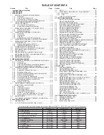

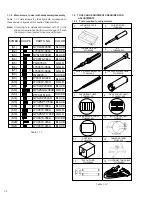


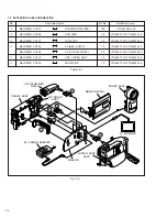

1-1
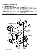
1
UPPER CASE(2)
Fig.1-3-2
2(S1), (L1)
NOTE1
2
UPPER CASE(1)
Fig.1-3-3
(S1), (L2)
NOTE1,2
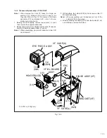
3
TOP COVER
Fig.1-3-4
(S1), 2(S2), (L1), (L3), 2(L4)
NOTE3,4
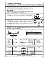
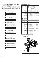
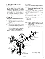
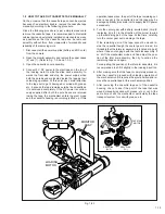
1.1.3 Disconnection of Connectors (Wires)
Connector
Pull both ends of the connector in the arrow direction, re-
move the lock and disconnect the flat wire.
Fig. 1-1-1 Connector 1
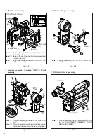
Fig. 1-1-2 Connector 2
Extend the locks in the direction of the arrow for unlocking
and then pull out the wire. After removing the wire, immedi-
ately restore the locks to their original positions because the
locks are apt to come off the connector.
(1)
Indicate the disassembly steps. When assembling, per-
form in the reverse order of these steps. This number
corresponds to the number in the disassembly diagram.
(2)
Indicates the name of disassembly/assembly parts.
(3)
Indicates the number in the disassembly diagram.
(4)
Indicates parts and points such as screws, washers,
springs which must be removed during disassembly/
assembly.
P
= Spring
W
= Washer
S
= Screw
Lock (L), soldering (SD), shield, connector, etc.
[Example] • Remove (W1) = Washer W1.
• Remove (SD1) = Soldering at the point SD1.
• Connector
A
= Disconnector the connector
A
.
(5)
Precautions on disassembly/assembly.
SECTION 1
DISASSEMBLY
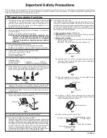
1.1 BEFORE ASSEMBLY AND DISASSEMBLY
1.1.1 Precautions
1. Be sure to remove the power supply unit prior to mount-
ing and soldering of parts.
2. When connecting and disconnecting the connectors, be
careful not to damage the wire.
3. When replacing chip parts (especially IC parts), desolder
completely first (to prevent peeling of the pattern).
4. Tighten screws properly during the procedures.
Unless specified otherwise, tighten screws at a torque
of 0.2N·m (2.0kgf·cm).
1.1.2 Assembly and disassembly
STEP
/LOC
PART
NO.
REMOVAL
Fig.
No.
UNLOCK/RELEASE/
UNPLUG/UNCLAMP/
Note
UNSOLDER
(1)
(2)
(3)
(4)
(5)
Connector
Flat wire
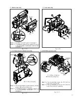
Fig. 1-1-3 Connector 3
Connector
Flat wire
▲
▲
▲
▲
▲
Connector
Flat wire