
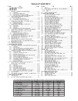


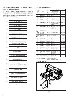


1-7
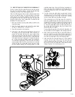
Note
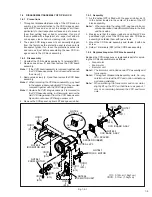
14: Bay head to the FPC wire not to damage it.
Note
15: For disassembling the Monitor assembly, refer to
"1.5 DISASSEMBLY/ASSEMBLY OF MONITOR
ASSEMBLY"
31
(S7)
30
(S1)
NOTE16
NOTE17
29
(S1)
11
✽✽
Fig. 1-3-10
-
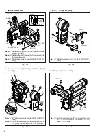
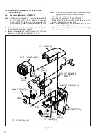
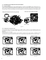
E. VF (electronic viewfinder) assembly
Fig. 1-3-12
Fig. 1-3-13
0
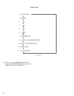
Monitor assembly
=
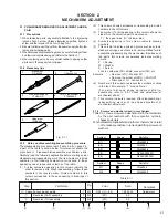
Frame assembly
~
JUNCTION board assembly
Fig. 1-3-11
✽✽
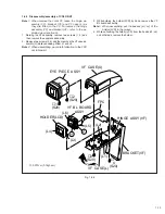
: 0.15N·m (1.5kgf·cm)
✽
: 0.07N·m (0.7kgf·cm)
✽✽✽
:0.05N·m (0.5kgf·cm)
NOTE15
28
(S1)
26
(S1)
27
(S1)
(L1)
10
NOTE14
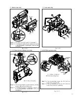
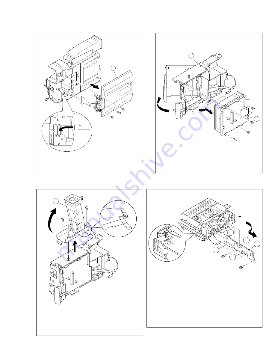
FPC
ASSY
FRAME
ASSY
(L12)
NOTE18
(L13)
NOTE19
O
13
L
O
M
N
36
(S8)
37
(S9)
✽
✽✽✽
Note
18: When reassembling secure the FPC with the
hook of the motor bracket.
Note
19: When reassembling, secure the FPC with the
hook of the catcher (T) assembly.
12
K
33
(S1)
32
(S1)
35
(S1)
34
(S1)
(L3)
Note
16: When reinstalling the monitor assembly, carefully
arrange allthe wires as they were.
Note
17: For disassembly the E. VF assembly, refer to "1.6
E. VF DISASSEMBLY/ASSEMBLY OF E. VF
ASSEMBLY"