background image

(No.86730)1-19

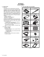
1. Alignment tape

To be used for check and adjustment of interchangeability of
the mechanism. 

2. Guide driver (Hexagonal)

To be used to turn the guide roller to adjustment of the linarity
of playback envelope.

3.INF adjustment lens

To be used for adjustment of the camera system. For the us-
age of the INF adjustment lens, refer to the Service Bulletin
No. YA-SB-10035.

4.INF lens holder

To be used together with the Camera stand (6) for operating
the Videocamera in the stripped-down condition such as the
status without the exterior parts or for using commodities that
are not yet conformable to the interchangeable ring. For the
usage of the INF lens holder, refer to the Service Bulletin No.
YA-SB-10035.

5.Camera stand

To be used together with the INF adjustment lens holder. For
the usage of the Camera stand, refer to the Service Bulletin
No. YA-SB-10035.

6.Light box assembly

To be used for adjustment of the camera system. For the us-
age of the Light box assembly, refer to the Service Bulletin No.
YA-SB-10035.

7.Gray scale chart

To be used for adjustment of the camera system. For the us-
age of the INF adjustment lens, refer to the Service Bulletin
No. YA-SB-10035.

8.Color bar chart

To be used for adjustment of the camera system. For the us-
age of the INF adjustment lens, refer to the Service Bulletin
No. YA-SB-10035.

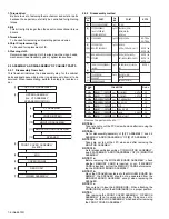
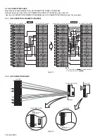
9. Jig connector cable 

Connected to CN105 of the main board and used for electrical
adjustment, etc.

NOTE:

Only some of the connectors in the JIG connector
(YTU93106B) are soldered to wires. 
 It is desirable that you solder all the connectors to wires before
using the JIG connector (YTU93106B), but you should solder
only the connectors shown in the following JIG connector
schematic diagram to wires because they are used in this
model.
 As for the details, see 3.3 JIG CONNECTOR CABLE.

10.Extension connector

Connect this extension connector to the connector of the jig
connector cable for extending the cable connector.

NOTE:

removing the cover (for jig), use this extension connector triple
for connecting the jig connector cable.

11.Communication Cable

Connect the Communication cable between the PC cable and
Jig connector cable when performing a PC adjustment.

12.PC cable

To be used to connect the Videocamera and a personal com-
puter with each other when a personal computer issued for ad-
justment.

13.Service support system

To be used for adjustment with a personal computer. Software
can be downloaded also from JS-net.

14.Cleaning cloth

Recommended the Cleaning cloth to wipe down the video
heads, mechanism (tape transport system), optical lens sur-
face.

Содержание GR-D20EK

Страница 1: ...Viewfinder Electronic viewfinder with 0 24 black white LCD Speaker Monaural Format DV format SD mode Signal format PAL standard Recording Playback format Video Digital component recording Audio PCM digital recording 32 kHz 4 channel 12 bit 48 kHz 2 channel 16 bit Cassette Mini DV cassette Tape speed SP 18 8 mm s LP 12 5 mm s Maximum recording time SP 80 min using 80 min cassette LP 120 min S Video...

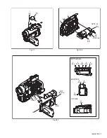
Страница 2: ...PEAKER is soldered to the MONI BW BOARD AS SEMBLY the SPEAKER should not be separated from the MONI BW BOARD ASSEMBLY except when replacing the SPEAKER NOTE 11c Take care not to lose the KNOB SLIDE When attaching the KNOB SLIDE attach the KNOB SLIDE in a proper position NOTE 3 After removing the FRONT COVER ASSEMBLY OP BLOCK ASSEMBLY is not covered with anything Take care not to damage the OP BLOC...

Страница 3: ...730 1 7 Fig C1 Fig C2 2 Fig C2 1 L1 S1 1 1 c NOTE 8a NOTE 8b 13 S8 12 S8 8 c L8 CN8a a b b a 7 2 8 12 S2c 2 S2a 3 S2b 8 S2d 10 S2e 11 S2c 9 S2d 4 S2b 5 S2c 6 S2c CN2a CN2b L2 TOP SIDE REAR SIDE BOTTOM SIDE c ...

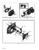
Страница 4: ...9 15 S9 0 147N m 1 5kgf cm L10 10 9 L9 CN10a 18 S10b 19 S10b NOTE 10b L CASE SIDE 28 S3 CN4 L3a OP BLOCK ASSEMBLY NOTE 3 L3b 4 3 4 29 S4 28 S3 COVER JACK e e 20 S11a 22 S11b 21 S11a 23 S11b 12 NOTE11b BKT HINGE 11 NOTE11c KNOB SLIDE 24 S11c 25 S11c 27 S11c 26 S11c NOTE 11a ...

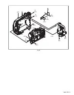
Страница 5: ... No 86730 1 9 Fig C4 6 34 S6 h g h g 35 S7a 38 S7b 32 S5b 31 S5b 33 S5b 37 S7b 36 S7b 30 S5a CN7a CN7b CN6 5 7 L5 f f ...

Страница 6: ...MBLY 3 4 PREMDA BOARD ASSEMBLY MECHANISM ASSEMBLY OP BLOCK ASSEMBLY MAIN BOARD ASSEMBLY OP BLOCK ASSEMBLY CCD BOARD ASSEMBLY PREMDA BOARD ASSEMBLY MECHANISM MAIN CN108 MAIN CN107 MAIN CN111 MAIN CN110 PREMDA CN406 PREMDA CN405 PREMDA CN404 PREMDA CN402 PREMDA CN403 PREMDA CN407 OP BLOCK ASSEMBLY CN501 CCD CN5001 PREMDA CN408 PREMDA CN401 SENSOR CAPSTAN MOTOR DRUM MOTOR HEAD LOADING MOTOR ROTARY EN...

Страница 7: ... No 86730 1 11 Fig D3 4 S3a 5 S3a L3 PREMDA BOARD ASSEMBLY 6 S3b 7 S3b 9 S4 0 069N m 0 7kgf cm 0 078N m 0 8kgf cm 8 S4 PR SHIELD COVER 4 BKT MECHA CN3a CN3b CN3c CN3e CN3f CN3d 3 10 S4 ...

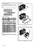
Страница 8: ... the LCD UNIT ASSEMBLY with the FPC NOTE 8c In attaching the LCD UNIT ASSEMBLY put the projec tions of the LCD UNIT ASSEMBLY in the slots of the BOTTOM CASE VF Put the STOPPER of the FPC in side the BOTTOM CASE VF In attaching the UPPER CASE VF F and the UPPER CASE VF R attach the UPPER CASE VF F first and then the UPPER CASE VF R and be careful to keep the FPC inside the BOTTOM CASE VF 2 4 2 Disa...

Страница 9: ... Remove one screw 5 and then remove the BL BOARD ASSEMBLY together with the BACK LIGHT ASSEMBLY NOTE 10a It depends on the inch size of the monitor assembly whether the backlight is supplied as an assembly or as separated parts In replacing the backlight assembly see the Parts List NOTE 10b Since the BACK LIGHT ASSEMBLY is soldered to the BL BOARD ASSEMBLY the BACK LIGHT should not be separated fr...

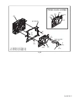
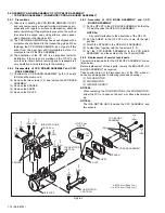
Страница 10: ...4 Remove the SHEET 5 Remove the OP LPF 2 6 3 Assembly of CCD BASE ASSEMBLY and CCD BOARD ASSEMBLY 1 Set the OP LPF to the OP BLOCK ASSEMBLY so that the OP side touches the OP BLOCK ASSEMBLY NOTE 2a Pay careful attention to the orientation of the OP LPF 2 Set the SHEET to the OP LPF not to come off the right position 3 Attach the SPACER to the OP BLOCK ASSEMBLY 4 Fasten them together with the two s...

Страница 11: ...Reference drawing Fig No Reference drawing Fig No Reference drawing Fig No Screw tightening torque Screw tightening torque Symbol No Removing order of screw Place to stick screw Symbol No Symbol No Removing order of screw Place to stick screw Reference drawing Fig No Screw tightening torque Symbol No Removing order of screw Place to stick screw MONITOR ASSEMBLY Removing order of screw Place to sti...

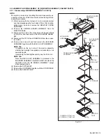
Страница 12: ...d at the unloading end 4 Apply DC 3V to the electrode on the top surface of the LOADING MOTOR ASSEMBLY to set the MECHANISM ASSEMBLY to the EJECT mode Unloading end is EJECT mode 5 If there is any slack tape in the tape transport system wind it inside the DVC CASSETTE TAPE by turning the REEL DISK ASSEMBLY SUP from the backside of the SLIDE DECK ASSEMBLY 6 Peel off the PVC TAPE and take out the DV...

Страница 13: ...idler gear does not engage with the reel disk well 2 Though the idler gear and reel disk are engaged with each other the tape is not wound because of overload to the mechanism 3 No FG pulse is output from the reel sensor 4 No power is supplied to the reel sensor 5 Tape transport operation takes place with a cassette having no tape inside 6 The tape slackens and no pulse is produced until the slack...

Страница 14: ...ent and adjustment etc a In case of wiring to chip test points for measurement use IC clips etc to avoid any stress b Since connectors are fragile carefully handle them in disconnecting and connecting c Short circuit between operation unit and DECK chas sis 2 Required test equipment a Color TV monitor b AC power adapter c Oscilloscope dual trace type observable 100 MHz or higher frequency It is re...

Страница 15: ...chart To be used for adjustment of the camera system For the us age of the INF adjustment lens refer to the Service Bulletin No YA SB 10035 9 Jig connector cable Connected to CN105 of the main board and used for electrical adjustment etc NOTE Only some of the connectors in the JIG connector YTU93106B are soldered to wires It is desirable that you solder all the connectors to wires before using the...

Страница 16: ...IN_VCO NC NC NC NC NC NC NC NC NC MONI_CHG GND NC NC ENV_OUT NC NC FS_PLL NC 1 2 3 4 5 6 7 8 9 10 11 12 13 14 15 AL_3VSYS CJIG_RST VIDL VCOM STH1 CVF_R CVF_B V_OUT GND MON_R MON_G CVF_G MON_B MONI_CHG JLIP_RX GND JLIP_TX PB_CLK HID1 GND ATFI ENV_OUT MAIN_VCO DISCRI I_MTR IF_TX EXMOD_0 FS_PLL MMOD_0 MMOD_1 16 17 18 19 20 21 22 23 24 25 26 27 28 29 30 1 2 3 4 5 6 7 8 9 10 11 12 13 14 15 16 17 18 19 ...

Страница 17: ...own is observed on the right hand side however straighten the level by turning the GUIDE ROLL ER TU of the POLE BASE ASSEMBLY 7 After adjustment try the unloading motion once and con firm that the waveform is flat straight when the tape has been played back again Moreover perform readjustment as required 8 When the recording has been played back again play back the self recording to confirm that t...

Страница 18: ... software for SERVICE SUPPORT SYSTEM properly Remove the COVER JIG to perform adjustment Fig 3 5 1 RED TO JLIP_RX WHITE BLACK TO JLIP_TX TO GND COMMUNICATION CABLE JIG CONNECTOR EXTENSION CONNECTOR Removing the cover for jig use this extension connector triple for connecting the jig connector cable NOTE JIG CONNECTOR CABLE COMMUNICATION CABLE CN105 COVER JIG SERVICE SUPPORT SYSTEM RS232C COM PORT ...

Страница 19: ...US_SW POW_LED ZOOM_SW IF_TX S_REEL AL_3VSYS DCO 0 3 JLIP_TX JLIP_RX T_BATT ADP_H JLIP_TX V_BATT T_REEL VF_CTL I_MTR S_DET CLK27SEL AREG_SO AREG_CLK SRV_TRK DAC_CS REG_CS ASPECT2 ASPECT1 LD_ON DYO 0 3 VPLN CLK27B FOCUS04 FOCUS03 FOCUS02 INV HDCVF P_DET DRUM_PWR DRUM_ERR FOCUS01 HALL_AD IRIS_O C CAP_PWR F Z_CS CAP_ERR IR_AMP REG_15V IR_OUT CAM_OUT M_UNREG INH OUT_C 0 3 OUT_VS OUT_HS REG_3 1V REG_2 5...

Страница 20: ...G M_UNREG DRUM_REF L_FRB T_REEL MDA_PS LD_ON DRUM_PWR DRUM_PWR DRUM_PWR CAP_ERR ENV_OUT ATFI REG_3 1V REG_3 1V GND GND GND GND RG H1 H2 CCD_ 7V SUB M_RVS SPK SPK VF_SW VCOM GND GND GND LCD_CTL M_REG4 8 M_REG4 8 MON_B LCD_B LCD_G LCD_R MON_G M_REG4 8 CAP_REF MON_R VIDL CVF_B CVF_G CVF_R STH1 REG_4 8V HDCVF REG_3 1V LV_OUT LV_CLK M_CS VDCVF KEY_A HRP REG_12V REG_15V VF_LCD REG_ 15V GND GND VFREG4 8 ...

Страница 21: ... BZ_FREQ ADM12 ADM11 TDO TCK TMS TDI TRSTL S_DET P_DET ADP_H BATT_H CHRG_LED RSV RSV RSV MENU_P_B MENU_P_A REMOTE ROM_CS M_CS VF_LCD LCD_CTL VF_CTL M_RVS VENC_CS VIF_DAC_CLK VIF_DAC_OUT VIF_IN EXT_IN_L TG_RST CCD_CTL DAC_CS AVREFOFF DSP_RST IRIS_O C S_IN_L RSV REG_RTC_CLK REG_RTC_OUT RTC_IN LV_CLK LV_OUT LV_IN MFLD FRP TSR SRV_TRK SPA DRUM_FG PD_L S_REEL T_REEL ND ND ND ND ND ND ND ND ND ND ND ND ...

Страница 22: ...2213 R2207 R2206 R2211 R2210 R2209 R2208 C2212 C2216 C2211 C2215 EM_AU R EM_AU L D2202 GND R2225 R2226 MIC R Q2202 R2230 R2229 R2231 A_MUTE Q2403 C2614 C2615 SPK SPK MIC_GND MIC L C2205 C2204 R2213 C2218 AK4564VQ 6 3 T 6 3 T 2SC4617 QR X NQL402M 100X 6 3 T NQL402M 100X 6 3 T 6 3 UMX1N W 2SC4617 QR X T 10 1 8k 1 8k 0 001 0 015 0 015 0 001 0 0047 0 0047 1 0 22k 22k 2 2k 2 2k 1 0 1 0 680k 39k 0 1 0 1...

Страница 23: ... N C VDDE VSS VSS VDDI VDDE VDDI VSS VSS MTEST PHYAVD2 BUSRST PMODE VDDI PHYAVD3 PWR3 PHYAVS2 PWR1 PWR2 PHYAVS1 PHYAVD1 VSS VSS VDDE VDDI JCY0152 NQR0129 002X NQR0006 001X 6 3 T BU2501FV X 4 T CH CH NAX0480 001X NQR0006 001X 6 3 T 2SC4617 NRZ0040 0R0X NQR0129 002X 6 3 T 2SC4617 NQR0129 002X RB751V 40 X NQR0006 001X CH ADVIN0 ADAVD0 ADAVS0 ADVRH0 ADVRL0 EXDATAI7 EXDATAI6 EXDATAI5 EXDATAI4 EXDATAI3 ...

Страница 24: ...CSO2 CSO3 YSO0 YSO1 YSO2 YSO3 OUTH VDD C VSS OUTV ZCNT RESVD RESHD MONI1 MONI2 SDOUT SDIN SCLK CS VDD I VSS RST ABAR2 COMP2 CBOUT VREF2 COUT AVDD DA AVSS IREF1 YCOUT ABAR1 COMP1 YSOUT VREF1 AVSS AVDD DA CLPY VYIN AVSS AVDD AD VRM VRL VRH CIN AVDD AD JCP8045 NQR0006 001X 6 3 T 4 T NQR0129 002X NQR0129 002X MM1504XN X IN2 H IN1 L GND VCC OUT SW UMZ1N W CH CH DTC144EE X CH CH UMZ1N W HDCVF VDCVF CSYN...

Страница 25: ...D VOUT VDD R1160N151B X 6 3 T NQR0129 002X NQR0129 002X CK D GND VCC PR CLR Q Q DRDVDD DVSS ADCLK DVDD PBLK OBP SPBLK SPSIG AVSS VRM VRT VRB DVDD DVSS CS SDATA SCK D0 VDDS VSS VDDS VDDS VDDS VDDS VDDS VSS VSS VSS VSS VSS NC VDDC VGND DSYO0 DSYO1 DSYO2 DSYO3 DSYO4 DSYO5 DSYO6 DSYO7 NC DSCO0 DSCO1 DSCO3 DSCO2 DSCO4 DSCO5 DSCO6 DSCO7 VDDC NC NC DSYIO0 DSYIO1 DSYIO2 DSYIO3 DSYIO4 DSYIO5 DSYIO6 DSYIO7 ...

Страница 26: ...6 IC3731 IC3801 REG_4 8V REG_4 8V REG_1 8V DSC AV STRM Q2401 Q2403 IC2201 REG_3 1V REG_3 1V REG_3 1V Q3731 Q3735 REG_3 1V IC3701 Q3701 Q3702 Q3704 Q3075 2 1 1 REG_3 1V 1 1 REG_3 1V IC5501 X5501 REG_1 8V REG_3 1V REG_4 8V REG_3 1V CAMERA DSP OP DRIVER FF_VCC L4802 IC4807 Q4803 Q4804 IC4802 IC4804 Q4801 Q4806 REG_3 1V CPU REG_3 1V AL_3 1V Q1009 AL_3 1V IC1004 IC1005 Q1004 Q1009 IC1008 IC1002 Q1001 Q...

Страница 27: ...3801 1 A D D A CONV 34 63 83 96 30 31 60 81 YSI0 YSI3 CSI0 CSI3 3 4 39 66 1 2 38 65 YSO0 YSO3 CSO0 CSO3 OUTH 86 INH OUTV 40 INV CLK 10 INH 36 OUT_HS INV 37 OUT_VS ZCNT 41 TBCCTL 92 YCOUT 75 CBOUT 51 CROUT TO CAMERA DSP TO CAMERA DSP DVMAIN BUF Q3704 BUF Q3705 YCOUT B Y_OUT R Y_OUT BUF Q3705 4 5 1 2 S_SHUT TO DSC TO AUDIO 1 WITH ANALOG INPUT MODEL 2 WITHOUT ANALOG INPUT MODEL 3 WITH EDIT MODEL 4 WI...

Страница 28: ...182 127 138 204 221 IC8004 TO IC8003 12PIN 1 3 YIO0 YIO7 CIO0 CIO7 YIN0 YIN7 CIN0 CIN7 CLKIN1 HDIN VDIN FID MXI CLKIN2 GIO0 GIO18 SCLK1 SDI1 26 28 11 12 FLSH_CE FLSH_OE FLSH_WE RESET SDO1 GIO13 RESET GIO16 GIO7 GIO11 USB_DN USB_DP FROM RAS WE CS CAS CKE CLK A0 2 DQ0 16 159 51 2 3 49 30 177 201 160 200 193 180 SDRAM_DATA SDRAM_ADRESS IC8002 SDRAM CXO X8002 48MHz 2 MMC_CLK 5 7 9 174 173 250 117 SDI3...

Страница 29: ... 8 0 3 0 9 0 0 10 3 3 1 11 1 6 0 12 3 3 1 13 0 0 14 1 3 0 15 0 0 16 3 1 3 1 17 2 3 0 18 2 3 0 19 2 4 0 20 0 0 21 0 0 22 1 2 1 4 23 0 0 24 3 3 1 25 0 0 6 26 3 1 0 27 2 5 0 28 0 0 29 0 0 30 0 3 0 31 0 3 32 3 0 33 3 3 1 34 1 5 0 35 1 3 1 4 36 3 3 1 37 0 0 38 0 0 39 0 0 40 0 3 0 41 7 1 0 42 0 3 15 1 43 15 1 15 1 44 7 1 15 1 45 7 1 15 1 46 7 6 7 6 47 0 0 48 3 3 MODE REC PLAY PIN NO REG MODE REC PLAY PI...

Страница 30: ...1 169 170 170 196 215 ASSEMBLY 04 203 198 MAIN BOARD ASSEMBLY 06 194 195 219 RATING LABEL 252 253 254 255 256 256 258 W1 155B 156A 156A 156B 215A 215B 215D 215C 215C 191A 191A 191A 167 167 168 165 155A 172 165H 165C 165G 165A 165B 165D 165K 165F 165J f 165L W2 W2 F4 F1 F1 h F8 F9 F9 F8 155B 165L 165E 㨏 b f 165J 165H 160 g 117 e a d F6 a b c d F1 k F15 ASSEMBLY M3 F14 F10 F12 F13 F11 F11 F12 F13F14...

Страница 31: ...L CASE SIDE 178 119 147 148 146 117 118 116 118 116 147 UPPER ASSEMBLY 109 F2 o MONITOR 104 101 102 102 106 104 m 110 106 n q 114 127 126 F3 108 n 105 115 125 F2 m ELECTRONIC VIEW 125 o F3 ASSEMBLY M5 FINDER ASSEMBLY M4 MONI BW BOARD ASSEMBLY 02 101A 101E 101A 101F F4 110 p 111 111 q 108 108 108 103 p e ...

Страница 32: ...greasing areas NOTE2 Mark is not contained in 900A 940 940 938 949 956 950 951 942 943 951 939 901 902 902 907 906 906 902 920 904 903 905 917 963 918 919 921 921 922 913 913 914 912 909 978 911 916 915 977 910 908 963 962 964 933 932 947 948 946 966 945 944 959 958 960 941 957 955 952 953 953 931 936 937 937 925 924 937 936B 936A 936B 928 929 954 934 935 961 963 965 BB AA AA AA CC AA CC CC CC CC ...

Страница 33: ... 4 ELECTRONIC VIEWFINDER ASSEMBLY M4 308 310 317 309 310 319 319 319 319 319 319 319 318 301 b a 304 316 316 a b 300 306 302 303 305 307 312 314 314 316 316 316 315 313 311 316 318C 318B 318A B W VF BOARD ASSEMBLY 07 ...

Страница 34: ...o 86730 1 5 MONITOR ASSEMBLY 2 5 INCH M5 513 502 510 512 BL 2 5 BOARD 504 504 503 501 500 503 b a 508 506 507 㨏 㨏 501C 501B 501A 501D 501D 501E d d 515A 515C 515C b a 515 515B ASSEMBLY 03 518 516 516 514 517 ...

Страница 35: ...102 LY30018 0D6A SPECIAL SCREW x2 103 LY33044 001D BKT HINGE2 5 104 LY30018 096A SPECIAL SCREW x2 105 QAS0126 001 SPEAKER 106 LY30018 017A SPECIAL SCREW x2 108 LY30018 059A SPECIAL SCREW x4 109 LY33049 002A COVER UPPER2 5 110 LY30018 056A SPECIAL SCREW x2 111 LY30018 0E6A SPECIAL SCREW x2 112 LY33050 002C COVER JIG 114 QUQ105 4007AA FFC WIRE MONI CN761 MAIN CN101 115 LY33033 001A ORNAMENT 2 5 2 A ...

Страница 36: ...SLIT WASHER 930 LY43684 001A TENSION CONTROL LEVER ASSY 931 LY32861 001A CENTER GEAR 932 LY31516 001F PINCH ROLLER ARM FINAL ASSY 933 YQ44246 SLIT WASHER 934 LY43681 001A TENSION CONTROL PLATE ASSY 935 LY43687 001A BRAKE CONTROL LEVER ASSY 936 LYH30421 001A MOTOR BRACKET ASSY SymbolNo Part No Part Name Description Local 936A QAR0138 001 LOADING MOTOR 936B LY41940 001A TAPPING SCREW x2 937 YQ43893 ...

Страница 37: ...3005 JCY0136 X IC IC3701 BA7665FS X IC IC3851 JCP8055FP IC IC4201 HD49340NP X IC IC4202 MM1613AN X IC IC4301 JCY0200 IC IC4302 R1160N151B X IC IC4802 BA10358FVM W IC IC4803 BA10358FVM W IC IC4804 UPC358G2 5 W IC IC4851 UPD16879GS X IC IC5501 JCY0185 IC IC6001 FA3698F IC IC6801 R1224N102G X IC IC8701 PIX MC10 IC F G H J IC8702 MT48LC1M16TG 6S IC F G H J Q1001 DTA114EE X DIGI TRANSISTOR Q1001 or PDT...

Страница 38: ...J 470W C CAPACITOR 47pF 50V J C1046 NCF31AZ 105X C CAPACITOR 1uF 10V Z C1047 NCFA1HZ 103W C CAPACITOR 0 01uF 50V Z C1048 NCFA1HZ 103W C CAPACITOR 0 01uF 50V Z C1049 NCFA1HZ 103W C CAPACITOR 0 01uF 50V Z C1050 NCFA1HZ 103W C CAPACITOR 0 01uF 50V Z C1051 NCB31CK 223X C CAPACITOR 0 022uF 16V K C1052 NCB31CK 223X C CAPACITOR 0 022uF 16V K C1053 NCB31CK 223X C CAPACITOR 0 022uF 16V K C1054 NCB31CK 223X...

Страница 39: ...No Part Name Description Local C4307 NCBA1AK 104W C CAPACITOR 0 1uF 10V K C4308 NCBA1AK 104W C CAPACITOR 0 1uF 10V K C4309 NCBA1AK 104W C CAPACITOR 0 1uF 10V K C4310 NCBA1AK 104W C CAPACITOR 0 1uF 10V K C4311 NCBA1AK 104W C CAPACITOR 0 1uF 10V K C4312 NCBA1AK 104W C CAPACITOR 0 1uF 10V K C4313 NBE20JM 106X TA E CAPACITOR 10uF 6 3V M C4314 NCBA1AK 104W C CAPACITOR 0 1uF 10V K C4315 NCBA1AK 104W C C...

Страница 40: ... R1038 NRSA6AJ 104W MG RESISTOR 100kΩ 1 16W J R1039 NRSA6AJ 152W MG RESISTOR 1 5kΩ 1 16W J R1040 NRSA6AJ 104W MG RESISTOR 100kΩ 1 16W J R1041 NRSA6AJ 0R0W MG RESISTOR 0Ω 1 16W J R1042 NRSA6AJ 0R0W MG RESISTOR 0Ω 1 16W J R1043 NRSA6AJ 102W MG RESISTOR 1kΩ 1 16W J R1044 NRSA6AJ 104W MG RESISTOR 100kΩ 1 16W J R1045 NRSA6AJ 105W MG RESISTOR 1MΩ 1 16W J R1046 NRSA6AJ 104W MG RESISTOR 100kΩ 1 16W J R104...

Страница 41: ...W J R3704 NRSA6AD 301W MG RESISTOR 300Ω 1 16W D Symbol No Part No Part Name Description Local R3705 NRSA6AD 301W MG RESISTOR 300Ω 1 16W D R3706 NRSA6AJ 332W MG RESISTOR 3 3kΩ 1 16W J R3707 NRSA6AD 680W MG RESISTOR 68Ω 1 16W D R3708 NRSA6AD 680W MG RESISTOR 68Ω 1 16W D R3709 NRSA6AD 680W MG RESISTOR 68Ω 1 16W D R3710 NRSA6AJ 104W MG RESISTOR 100kΩ 1 16W J R3711 NRSA6AJ 104W MG RESISTOR 100kΩ 1 16W ...

Страница 42: ...ESISTOR 18kΩ 1 16W D R6303 NRSA6AD 472W MG RESISTOR 4 7kΩ 1 16W D R6305 NRSA6AJ 104W MG RESISTOR 100kΩ 1 16W J R6306 NRSA6AJ 123W MG RESISTOR 12kΩ 1 16W J R6308 NRSA6AJ 473W MG RESISTOR 47kΩ 1 16W J R6309 NRSA63J 0R0X MG RESISTOR 0Ω 1 16W J R6402 NRSA6AD 243W MG RESISTOR 24kΩ 1 16W D R6403 NRSA6AD 302W MG RESISTOR 3kΩ 1 16W D R6405 NRSA6AJ 123W MG RESISTOR 12kΩ 1 16W J R6406 NRSA6AJ 103W MG RESIST...

Страница 43: ...bolNo Part No Part Name Description Local PW1 YB10433E MONI BW BOARD ASSY IC7601 AN12550A IC IC7602 BA4558F X IC Q7601 2SC4617 QR X TRANSISTOR Q7601 or 2SC4738 YG X TRANSISTOR Q7601 or 2SD2216J QR X TRANSISTOR Q7601 or BC847BT X TRANSISTOR Q7602 2SA1774 QR X TRANSISTOR Q7602 or 2SA1832 YG X TRANSISTOR Q7602 or BC857BT X TRANSISTOR Q7603 2SC4617 QR X TRANSISTOR Q7603 or 2SC4738 YG X TRANSISTOR Q760...

Страница 44: ...R FFC FPC 1 20 CN765 QGF0506F2 32X CONNECTOR FFC FPC 1 32 SW2 NSW0145 001X TACT SWITCH STOP SW3 NSW0145 001X TACT SWITCH REW SW4 NSW0145 001X TACT SWITCH FF SW5 NSW0145 001X TACT SWITCH PLAY PAUSE SW7 NSW0145 001X TACT SWITCH INDEX SW8 NSW0145 001X TACT SWITCH SELECT SW7601 NSW0200 001X LEVER SWITCH MONI SW SymbolNo Part No Part Name Description Local PW1 YB20938A BL 2 5 BOARD ASSY IC7604 DN8797MS...

Страница 45: ...MG RESISTOR 0 33Ω 1 4W F R1620 NRSA63J 103X MG RESISTOR 10kΩ 1 16W J R1621 NRSA63J 103X MG RESISTOR 10kΩ 1 16W J R1622 NRSA63J 103X MG RESISTOR 10kΩ 1 16W J R1624 NRSA63D 183X MG RESISTOR 18kΩ 1 16W D R1625 NRSA63D 361X MG RESISTOR 360Ω 1 16W D R1629 NRSA63J 564X MG RESISTOR 560kΩ 1 16W J R1630 NRSA63J 0R0X MG RESISTOR 0Ω 1 16W J R1631 NRSA63J 0R0X MG RESISTOR 0Ω 1 16W J Symbol No Part No Part Nam...

Страница 46: ... 1 16W J L501 NQR0251 004X FERRITE BEADS L502 NQR0251 004X FERRITE BEADS L503 NQR0251 004X FERRITE BEADS CN501 QGF0503C1 22X CONNECTOR FFC FPC 1 22 J501 QNS0078 001 3 5 JACK J502 QND0004 001 S JACK J503 PEMC1203 MINI JACK SW501 NSW0122 001X DETECT SWITCH EJECT SW SymbolNo Part No Part Name Description Local PW1 YB20940A B W VF BOARD ASSY Q7001 PUMX1 W PAIR TRANSISTOR Q7001 or BC847S X PAIR TRANSIS...

Отзывы: