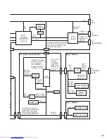
(No.MB160)1-37
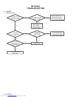
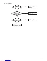
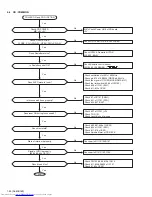
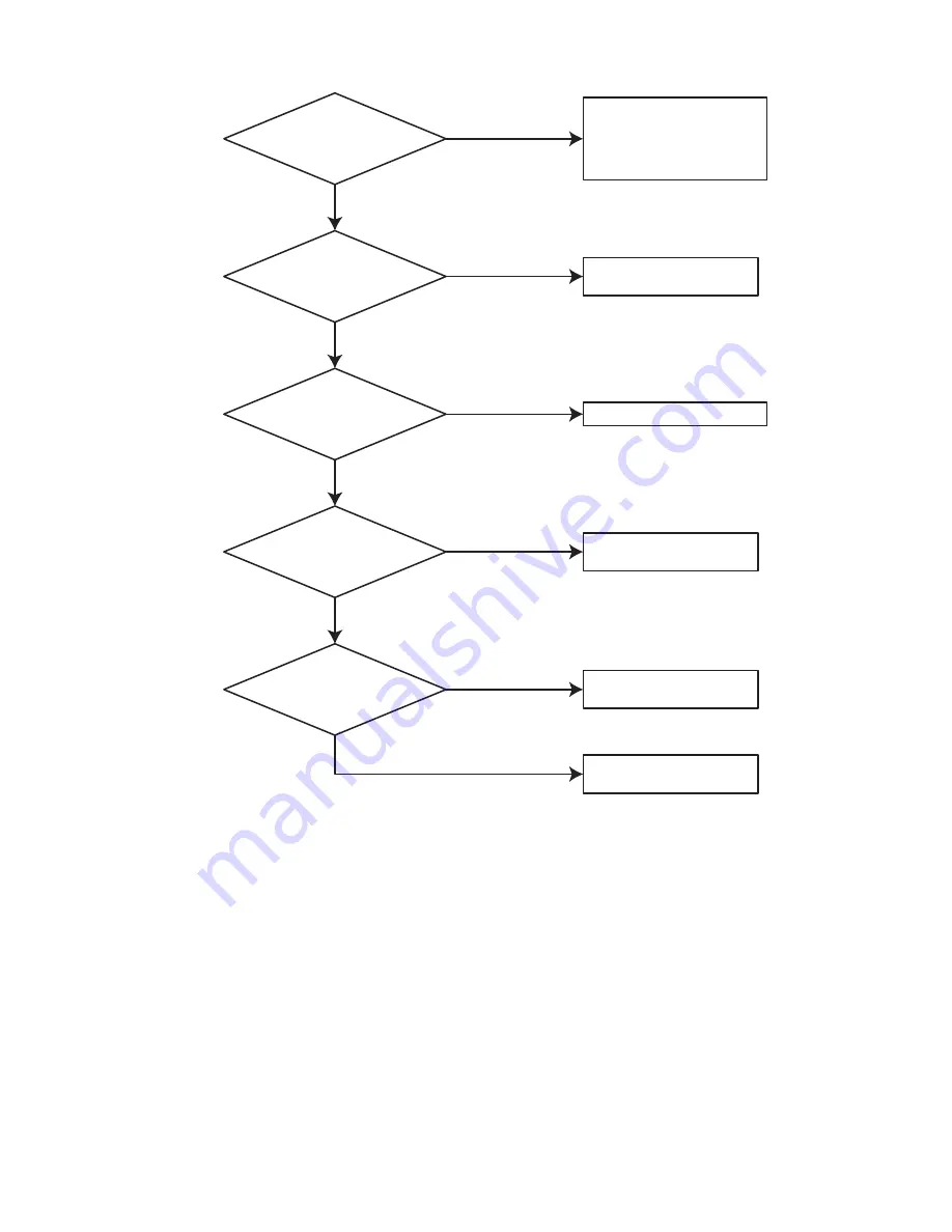
(2) No output (U/E version)
Amplifier board
(1) FIC01 : pin #2,3
(2) WIC01 : pin #1,#2
B+,B- normal?
AQ 5L,5R,AQ 603
Emitter B+?
No
Yes
Check the B+,B- Power source
PBD01,PBD02,RFS9
Check the Power board
Fude,P/T,RFS2,RFS5,
RFS6,RFS7,RFS8
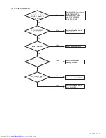
No
Is Mute selected?
Yes
Remove it with Remocon.
Yes
Headphone Jack short?
No
Check Headphone jack
soldering condition.
Yes
No
UIC2 (PT8300) pin 17
Check the "H"?
Yes
Check the Amplifier board
FIC01,WIC01
Check the Front board
UIC1 (micon), UIC3 (PT8300)
No
Check the Amplifier board
AQ5L,5R,AQ603
Содержание CA-MXGB5
Страница 45: ... M E M O ...
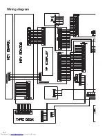
Страница 46: ...2 1 Wiring diagram ...
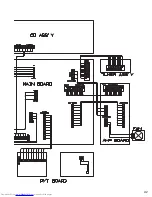
Страница 47: ...2 2 ...
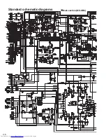
Страница 50: ...2 5 Standard schematic diagrams Main section MX GB6 ...
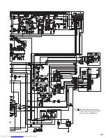
Страница 51: ...2 6 Parts are safety assurance parts When replacing those parts make sure to use the specified one ...
Страница 53: ...2 8 safety assurance parts placing those parts make se the specified one ...
Страница 54: ...2 9 Main section MX GB5 ...
Страница 55: ...2 10 Parts are safety assurance parts When replacing those parts make sure to use the specified one ...
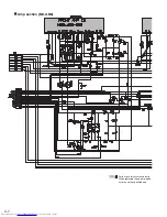
Страница 56: ...2 11 Parts are safety assurance p When replacing those parts sure to use the specified on Amp section MX GB5 ...
Страница 57: ...2 12 arts are safety assurance parts hen replacing those parts make re to use the specified one ...
Страница 58: ...2 13 FL Key control section common ...
Страница 59: ...2 14 ...
Страница 60: ...2 15 CD section common ...
Страница 61: ...2 16 ...
Страница 62: ...2 17 Printed circuit boards Main board ...
Страница 63: ...2 18 Amp board ...
Страница 64: ...2 19 Front board ...
Страница 65: ...2 20 CD board ...

