(No.MB160)1-27
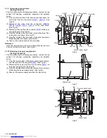
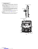
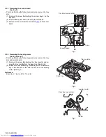
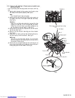
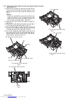
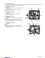
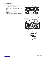
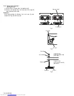
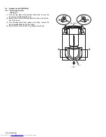
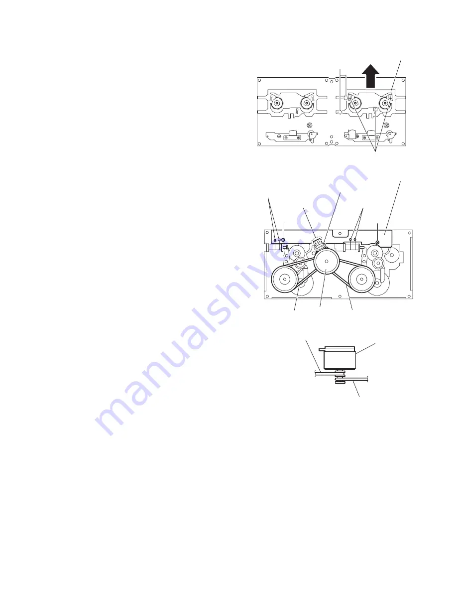
3.4.4 Removing the motor
(See Figs.4 to 6)
(1) Slide the plastic cover in the direction of the arrow and re-
move the three claws
a
to remove the plastic cover.
(2) Remove the two screws
D
fixing the motor.
Note:
Be careful to grease's splash when the drive belt comes
off.
(3) Unsolder the motor terminal.
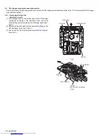
3.4.5 Removing the mechanism board
(See Fig.5)
(1) Unsolder the four solder parts
b
and four solder parts
c
.
(2) Remove the two screws
E
attaching the mechanism board.
Fig.4
Fig.5
Fig.6
Plastic cover
Claws
a
D
Motor terminal
Motor
Drive belt
Drive belt
Mechanism board
Solder parts
b
Solder parts
c
Solder parts
c
E
E
Drive belt
Drive belt
Motor
Содержание CA-MXGB5
Страница 45: ... M E M O ...
Страница 46: ...2 1 Wiring diagram ...
Страница 47: ...2 2 ...
Страница 50: ...2 5 Standard schematic diagrams Main section MX GB6 ...
Страница 51: ...2 6 Parts are safety assurance parts When replacing those parts make sure to use the specified one ...
Страница 53: ...2 8 safety assurance parts placing those parts make se the specified one ...
Страница 54: ...2 9 Main section MX GB5 ...
Страница 55: ...2 10 Parts are safety assurance parts When replacing those parts make sure to use the specified one ...
Страница 56: ...2 11 Parts are safety assurance p When replacing those parts sure to use the specified on Amp section MX GB5 ...
Страница 57: ...2 12 arts are safety assurance parts hen replacing those parts make re to use the specified one ...
Страница 58: ...2 13 FL Key control section common ...
Страница 59: ...2 14 ...
Страница 60: ...2 15 CD section common ...
Страница 61: ...2 16 ...
Страница 62: ...2 17 Printed circuit boards Main board ...
Страница 63: ...2 18 Amp board ...
Страница 64: ...2 19 Front board ...
Страница 65: ...2 20 CD board ...

