Chapter 2—Functional Descriptions
2-72
Model 330. 340SC, and 370SC Service Manual
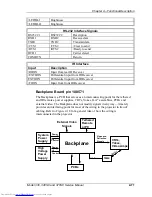
Figure 2-18
Backplane Interface Block Diagram
2.7 Optical
Section
The Optical section consists of the CRT Assembly, the Arc Lamp Assembly, and
the Optical subassemblies, which provides the image to be viewed on the screen.
The Optical Section filters, splits and directs the high intensity light to the three
(3) separate (RGB) light channels. Figure 2-19 shows the video path from the
CRT to the screen and the optical path from the Arc Lamp to the screen.
CRT Assembly
The image in the projector begins at the three (3) CRTs. The CRT Assembly is
located beneath the main electronics card cage and contains three (3) sets of the
following:
CRT tubes.
CRT cooling assemblies.
CRT Yokes.
Yoke clamps.
Video Amplifier Boards.
Each CRT has a high resolution infrared beam and a high resolution phosphor
screen. Fans mounted at the rear of the assembly cool the CRT Assembly.
Procedures for adjusting the yokes and the width coils can be found in
Section.3.2. A functional description of the Video Amplifier Boards is provided in
Section 2.6.5.
Relay Lens
The relay lens picks up the CRT image from the face of the CRT and focuses the
image to the ILA
®
assembly.
Image Light Amplifier (ILA
®
) Assembly
At the same time as the image is received at the input side of the ILA
®
assembly,
the output side of the ILA
®
assembly is receiving high intensity light from the arc
lamp through the prism. This high intensity light is then phase modulated (altered)
by the video signal from the input side of the ILA
®
assembly and then reflected
back out of the output side and then travels through the prism to be picked up by
the projection lens.
NOTE:
The prism reflects horizontally polarized light and passes vertically
polarized light. Light from the arc lamp is polarized horizontally and reflects from
the prism into the ILA
®
assembly then back out again, after being phase
modulated 90° to vertical by the Liquid Crystal layers into vertically polarized
Содержание 330
Страница 9: ...Safety xi Model 330 340SC and 370SC Service Manual ...
Страница 113: ...Chapter 3 Service Adjustments Model 330 340SC 370SC Service Manual 3 23 ...
Страница 137: ...Chapter 4 Maintenance 4 24 Model 330 340SC 370SC Service Manual Table 4 2 for reference to part numbers if necessary ...
Страница 163: ...Glossary Model 330 340SC and 370SC Service Manual ...


