Chapter 2—Functional Description
Model 330, 340SC and 370SC Service Manual
2-65
each line in the raster. The starting address is timed by the /MAPST signal. When
that comes along, it indicates the top of the raster is beginning so the address
generator should begin counting at the beginning.
Overlay Interface
The Overlay Interface takes the raw data out of the Overlay Memory and sends
formatted information to the VPB for generating the desired displays. Some of the
data is simply buffered and sent along. That data is the information regarding the
full brightness and external video that produces everything but greyscale and dots.
The greyscale, dot, and pyramid patterns must first be decoded by a D to A. After
conversion to analog and appropriate filtering, the information is sent out to the
VPB as the VIDTEST signal.
LED Display Buffers and Logic
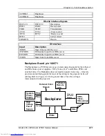
The LED dot matrix display is located on the rear of the projector just under the
video and sync input connectors. In that location, it is not physically located on
the SCB but it is directly controlled by the CPU with connection via the
backplane.
The Dot Matrix Display is used for displaying operational and error codes. These
codes will assist in troubleshooting and verifying proper operation. The Dot
Matrix Display receives its data from the CPU via the display buffer.
RS232 Interface
The RS232 Interface is a bi-directional communications port. The interface
protocol is RS232 with two (2) ports; one (1) port being fully functional with the
other having more limited use.
The Terminal In port is the fully functional port. It is used for communicating
with the projector using a VT100 or similar terminal emulator. The terminal
allows accessing all functions available on the projector. In addition, using the
terminal provides the user with continuously updated status data. The bi-
directional port allows third-party controllers to be used to control the projector
using ASCII character control codes.
The Terminal Out port is also RS232 but has limited functionality. It is used
primarily for attaching a switcher to the projector to allow for smoother switching
of sources.
IR Interface
The IR Interface is a receive-only interface. There is no capability to transmit
information out of the projector over the IR interface. The user must depend on
the on-screen information and LED Dot Matrix displays to verify operation of the
projector.
Содержание 330
Страница 9: ...Safety xi Model 330 340SC and 370SC Service Manual ...
Страница 113: ...Chapter 3 Service Adjustments Model 330 340SC 370SC Service Manual 3 23 ...
Страница 137: ...Chapter 4 Maintenance 4 24 Model 330 340SC 370SC Service Manual Table 4 2 for reference to part numbers if necessary ...
Страница 163: ...Glossary Model 330 340SC and 370SC Service Manual ...


