background image

45

INSTALLING (JLIP Player Software)

WINDOWS

T

 95

Refer to the Windows

T

 95 manual or your

computer’s manual for details on basic
Windows

T

 95 operating procedures.

Installation Procedure

This software offers you the choise of viewing
on-screen messages in English or French.
Select the desired language during installa-
tion by performing the following steps.
*To start the setup program...

1

Launch Windows

T

 95

•Close any other applications that are

running.

2

Insert the "VIDEO MOVIE PLAYER" CD-
ROM into the CD-ROM drive.

3

Choose "Run" from the "Start" on the
taskbar.

4

If you want English on-screen messages…

If the "VIDEO MOVIE PLAYER" CD-ROM
is in Drive D, type "D:\VMPE\SETUP" in
the box to the right of "Name". If the disk
is in Drive E, type "E:\VMPE\SETUP".

If you want French on-screen messages…

If the "VIDEO MOVIE PLAYER" CD-ROM
is in Drive D, type "D:\VMPF\SETUP" in
the box to the right of "Name". If the disk
is in Drive E, type "E:\VMPF\SETUP".

•Click "OK".
•Once the setup program is running,

simply follow the instructions displayed
on-screen.

•When setup is complete, the "MOVIE

PLAYER" icon appears on the screen.

•"MOVIE PLAYER Setup was completed

successfully." appears.

5

Click "OK" to complete installation.

WINDOWS

T

 3.1

Refer to the Windows

T

 3.1 manual of or your

computer manual for details on basic
Windows

T

 3.1 operating procedures.

Installation Procedure

This software offers you the choise of viewing
on-screen messages in English or French.
Select the desired language during installa-
tion by performing the following steps.
*To start the setup program...

1

Launch Windows

T

 3.1

•Close any other applications that are

running.

2

Insert the "VIDEO MOVIE PLAYER" CD-
ROM into the CD-ROM drive.

3

Choose "Run" from "File" in the "Program
Manager".

4

If you want English on-screen messages…

If the "VIDEO MOVIE PLAYER" CD-ROM
is in Drive D, type "D:\VMPE\SETUP" in
the box to the right of "Name". If the disk
is in Drive E, type "E:\VMPE\SETUP".

If you want French on-screen messages…

If the "VIDEO MOVIE PLAYER" CD-ROM
is in Drive D, type "D:\VMPF\SETUP" in
the box to the right of "Name". If the disk
is in Drive E, type "E:\VMPF\SETUP".
•Click "OK".
•Once the setup program is running,

simply follow the instructions displayed
on-screen.

•When setup is complete, the "MOVIE

PLAYER" icon appears on the screen.

•"MOVIE PLAYER Setup was completed

successfully." appears.

5

Click "OK" to complete installation.

NOTE : This instruction manual uses

English on-screen messages in its
explanation.

Содержание 0397MKV*UN*VP

Страница 1: ...GV DS1 JLIP VIDEO CAPTURE DOCKING STATION LYT0002 0J9A GV DS1 INSTRUCTIONS ...

Страница 2: ...ip ment If the plug fitted is not suitable for the power points in your home or the cable is too short to reach a power point then obtain an appropriate safety approved extension lead or consult your dealer BE SURE to replace the fuse only with an identical approved type as originally fitted and to replace the fuse cover If nontheless the mains plug is cut off ensure to remove the fuse and dispose...

Страница 3: ...ent DO be careful with glass panels or doors on equipment DON Tcontinue to operate the equipment if you are in any doubt about it working normally or if it is damanged in any way switch off withdraw the mains plug and consult your dealer DON Tremove any fixed cover as this may expose dangerous voltages DON Tleave equipment switched on when it is unattended unless it is specifically stated that it ...

Страница 4: ...TATION 1 DO NOT place the VIDEO CAPTURE DOCKING STATION in an environment prone to extreme temperatures or humidity in direct sunlight in a dusty environment in an environment where strong magnetic fields are generated on a surface that is unstable or subject to vibration The unit may fall causing injury 2 DO NOT place heavy objects on the VIDEO CAPTURE DOCKING STATION 3 DO NOT place anything whic...

Страница 5: ...y connected to the AC Power Adapter Charger When using the AC Power Adapter Charger use only the supplied Power Cord Use of any other cord may result in shock or fire Connect the Power Cord to the AC Power Adapter Charger before connecting it to an AC outlet If you plug it into an outlet first and the Adapter s terminals come in contact with a metal surface or object short circuit or fire may resu...

Страница 6: ...TO CLOSE THE PROGRAM 19 HOW THE DESKTOP WORKS 20 Main desktop window 20 Menu bar 21 VIDEO CAPTURE 24 Capturing video images 24 Step by step capture 25 Automatic capture 26 Program capture 26 Interval capture 28 SAVE PICTURE 29 Saving 29 Save the full image data 29 PICTURE FORMAT SETTING 30 Selecting a picture format 30 Delete index image and full image 31 Change ID 31 ADDITIONAL OPERATIONS 32 Coun...

Страница 7: ...STARTING JLIP PLAYER SOFTWARE 46 MOVIE PLAYER WINDOW BUTTONS AND DISPLAYS 48 BASIC OPERATIONS 50 VIDEO PRINTER WINDOW BUTTONS AND DISPLAYS 56 VIDEO PRINTER OPERATION GV PT2 58 Printing 58 Auto capture 60 ADVANCED OPERATIONS 62 Changing ID number 62 Connecting other device during operation 62 Changing the name of the device 63 Changing the device to use while connecting over two same type devices 6...

Страница 8: ...Advanced Applications Create title indexes for your video collection Title index images can be captured from your favorite recordings in intervals of 30 minutes 1 hour 1 5 hours etc using the Interval Capture mode Print the captured index images on your PC printer using the compu ter s Print Screen facility then attach them to your cassettes Video journal and postcards Create your own original pos...

Страница 9: ...pe scanning transferring to PC Data Sharing With JLIP Player Soft ware Data can be imported from the JLIP Player Software Data from the Video Capture Software can also be exported to the Player Software for Program Playback or Assemble Editing JLIP Player Software Z pg 41 65 JLIP Control Facility With a JLIP compatible camcorder VCR or video printer GV PT2 all basic video operations can be execute...

Страница 10: ... terminal COM port MULTI connector The Docking Station can be connected with the GR DVM1 through this connector Never touch it with your hand or hit it with a hard object if the pins are damaged the connectors will become unusable due to contact failure Stop button Play button Rewind button Pause button Fast forward button Edit start button JLIP jack Z p 13 JLIP Joint Level Interface Protocol Conn...

Страница 11: ... when a TV is not connected to the video printer this connection allows you to see the images output from the video printer on the LCD screen while printing The date and timecode are not shown on the LCD screen If you want to print out the date together with the images connect a TV to the video output connector of the video printer and operate it by referring to the TV screen It is also possible t...

Страница 12: ...en connecting the provided cables be sure to connect the terminals equipped with Core filters to the Video Capture Docking Station n When using the Video Capture Docking Station use the AA V80EK EA AC Adapter Charger provided with the camcorder Core filter PC connection cable provided To COM RS 232C port To Digital 8 pin connector Personal computer To VIDEO output jack To JLIP jack VCR Recording d...

Страница 13: ...C Adapter Charger Core filter To CAPTURE INPUT EXT PRINTER connector Other units with video output jack DC cable provided Core filter red white yellow AUDIO VIDEO cable provided Core filter To JLIP jack To DC output jack 3 5 mm diameter 4 pole cables provided ...

Страница 14: ...nvironment Personal computer with MicrosoftT WindowsT 3 1 or WindowsT 95 CPU Intel DX4 or higher processor Minimum RAM requirement more than 8 MB Available Hard Disk space of at least 8 MB Colour display capable of at least 640 x 480 pixels 256 colours Recommended 1024 x 768 16 77 Mil colours 1 free serial transmission port compatible with 9600 bps transmission rate connectable to RS 232C with 9 p...

Страница 15: ...etup was com pleted successfully appears 5 Click OK to complete installation WINDOWST 3 1 Refer to the WindowsT 3 1 manual of or your computer manual for details on basic WindowsT 3 1 operating procedures Installation Procedure This software offers you the choise of viewing on screen messages in English or French Select the desired language during installa tion by performing the following steps To...

Страница 16: ...on which the image is stored Close any programs that are running You cannot run other programs simultaneously with the Video Capture software With WindowsT 95 click the START button on the taskbar and the Program menu appears on the screen Move the mouse pointer over the program entry you want to run and click to start the program Now let s start the program If you re using WindowsT 3 1 open the J...

Страница 17: ...3 Select COM Port COM1 through COM4 ports are available Check to see which COM port is connected to the JLIP Video Capture Docking Station and select it 4 Select Transfer Rate Normally select 38400 38400 may not be available on some computers When transmission errors take place during use switch to 19200 or 9600 Image data transmission will be slower at these speeds 5 Click OK Call up the JLIP Ini...

Страница 18: ...e Only one VCR and one Video Capture device can be selected 8 Click OK The main desktop window returns setting complete NOTE The Device Selection window automatically appears when JLIP initialization is complete However if you want to select equipment whose JLIP initialization has already been carried out select Device Change from Set up in the menu bar to call up the Device Selection window Devic...

Страница 19: ...ou try to close the programme with no image data saved the message The album has not been saved Save appears Please note that if you close without saving all unsaved captured data will be deleted 1Click Exit from File in the menu bar The programme closes File New Album Open Album Save Album Open JLIP jlp File Save As JLIP jlp File Save Image As Exit Ctrl S Ctrl A ...

Страница 20: ...age from the video source JLIP button Z pages 41 through 65 The JLIP Video Capture software and JLIP Player software cannot run simultaneously When you want to run the JLIP Player software press this button to call up a cross bar and run the software To resume using the JLIP Video Capture software first select Close Serial from File on the JLIP Player Software s menu bar then press the JLIP button...

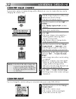
Страница 21: ...g on the program status Invalid commands appear lighter than valid commands File Edit Set up Window Help JLIP Video Capture New Album Open Album Save Album Open JLIP jlp File Save As JLIP jlp File Save Image As Exit Ctrl S Ctrl A INPUT MEMORY 02 00 02 17 21 03 00 07 01 19 04 00 37 05 06 Hatched like this when counter time is corrected Z p 32 Index numbers are automatically assigned Colours of coun...

Страница 22: ...ogram Z p 19 An index image of the image data in the Video Capture Docking Station memory is transferred to your computer and displayed in the selected image box in the Step by Step capture mode The video source unit scans the selected counter value and transfers the index image to your computer in the automatic capture mode Z p 32 A full image of the image data in the Video Capture Docking Statio...

Страница 23: ...indow appears to allow the computer to operate the VCR VCR operation window VCR models operable on the VCR Operation Window compatible with JLIP 00 01 23 12F I VCR Capture Transfer Counter display PLAY button Forward Slow button PAUSE button STOP button REW REW Search button FF FF Search button VCR POWER button Reverse Slow button Capture button Transfer button Help Contents About JLIP Video Captu...

Страница 24: ...image data with a resolution of 768 x 552 pixels 2 types of video data Bitmap data Approx 1 3MB JPEG video compression data Approx 50 kB Index image data with a resolution of 80 x 60 pixels When storing full image data on a 2HD disk An image saved in the bitmap data format can be stored on one disk About 28 images saved in the JPEG video compression format can be stored on one disk This is the cas...

Страница 25: ...ton full image data 768 x 552 pixels is captured into the Video Capture Docking Station memory Index image data 80 x 60 pixels is simultaneously transferred to the computer 3 Index image data is transferred to the computer The message No 1 index image being transferred appears during data transfer 4 The message Transfer the full image Yes No appears Click Yes Full image data 768 x 552 pixels is tr...

Страница 26: ...lick Image Format in Set up and select Field Picture in the Capture Mode Z p 30 1 Open the menu bar and click Setup Capture Mode Automatic The Automatic Transfer window appears 2 Select data to be transferred When you select Index Image index image data 80 x 60 pixels is trans ferred to your computer When you select Index Full Image both the index image data 80 x 60 pixels and full image data 768 ...

Страница 27: ...u want to capture full image data 768 x 552 pixels after capturing the Index Image in step 2 click Index Full Image and then click the Trans fer button 1 The message Index No 1 being scanned appears while the video source unit is scanning the picture to be captured 2 The message No 1 index image being transferred appears and then No 1 full image being transferred appears while the full image data ...

Страница 28: ...the Transfer button at the desired picture 1 The message No 1 index image being transferred appears while the index image data is being transferred to the computer 2 When you select Index Full Image in step 2 the message No 1 full image being transferred appears while the full image data is being transferred to the computer 3 The message Index No 2 being scanned appears while the video data are fa...

Страница 29: ...ommercially available image editing software you can create your own unique and highly personal illustrations and graphics for incorporation into everything from postcards to newsletters and Internet homepages File Save Image As Exit Ctrl S Ctrl A New Album Open Album Save Album Open JLIP jlp File Save As JLIP jlp File 1 Click the image display box of the Index No to be saved The image display box...

Страница 30: ... is a leading standard defining the compression and decompression of still color pictures The quantity of transferred data appears smaller because the images are compressed This results in a shorter transfer time Bitmap 9 bmp Transfer time is longer when you use this format because there is no data compression The benefit is that picture quality is maintained with no deterioration Bitmap is a data...

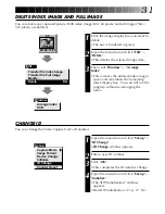
Страница 31: ...maining index display box You can still run the program without re arranging the index CHANGE ID You can change the Video Capture Unit s ID number Set up Capture Mode Image Format Device Change Initialize ID Change Counter Reset 1 Open the menu bar and click Set up ID Change ID Change window appears 2 Enter a new ID number 3 Click OK This completes the ID number change 4 Open the menu bar and clic...

Страница 32: ...ransfer the Index Image Index image data at the counter setting is captured Be sure to complete steps 1 through 7 If they are not all followed the index image and the full image will be different as the full image data will not have been changed in step 6 7 Click Edit Transfer the Full Image Full image data at the counter setting is transferred NOTE Note that if the index image data is saved in st...

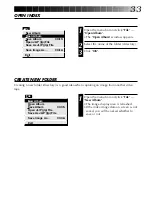
Страница 33: ... jlp File Save As JLIP jlp File CREATE NEW FOLDER Creating a new folder directory is a good idea when capturing an image from another video tape 1 Open the menu bar and click File New Album The image display area is refreshed If the index image data on screen is not saved you will be asked whether to save or not File Save Image As Exit Ctrl S Ctrl A New Album Open Album Save Album Open JLIP jlp Fi...

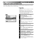
Страница 34: ...LIP jlp File window is displayed 2 Double click the name of the desired folder directory in the Select Directory box If the data is stored on a floppy disk enter the drive name 3 Click on the file name to select it 4 Click OK The computer monitor displays Scene No counter number at Edit in Point and a blank image box 5 Open the menu bar and click Set up Capture Mode Automatic 6 Select the data you...

Страница 35: ...ave As JLIP jlp File The Save As JLIP jlp File window is displayed 2 Enter the folder name directory and file name If you want to store the data on a floppy disk enter the drive name 3 Click OK The data converted to a JLIP Player software file is stored on the floppy disk in the selected drive JLIP Player software files can be used for video program editing or printed with the video printer Z p 58...

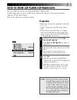
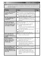
Страница 36: ... to check the images on the computer v When video equipment is connected to the CAPTURE EXT IN PRINTER connector its video is displayed on the LCD screen of the GR DVM1 v The counter display in the VCR operation window turns blue v Is your video unit compatible with JLIP Only JLIP compatible units can be operated If you are using a JLIP compatible unit and it still won t work check to make sure th...

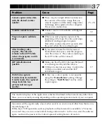
Страница 37: ...ere the recording begins v If you want to erase the file because of limited hard disk space start the program once then close it The video remaining in the JCPT folder will be cleared v Make sure that the IRQ Interrupt ReQuest is not being used by another device v COM port selection is wrong Confirm the COM port number and execute JLIP initialization again v In this case video capture is not possi...

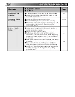
Страница 38: ...n Then turn on this unit and the connected devices v Video unit is brought to STOP or ends playback during automatic capture m Check the auto capture setting v Full image data 768 x 552 pixels cannot be captured if you start auto capture at the beginning of the tape Video capture stops if video playback is stopped m Start video capture 20 seconds after the start of the recording v Tape is too shor...

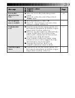
Страница 39: ...turn the Capture Docking Station off and then on again Images stored in memory will be lost m Do not use any other application while JLIP Video Capture and JLIP player are running as it may interfere with communication Do not click and move the mouse during data transfer v If your computer s energy saver battery voltage indication or screen saver is engaged the image data transmission may be inter...

Страница 40: ...40 MEMO ...
Страница 41: ...rmation for setup and information that is not included in the instruction manual Please read the file before installing the provided software program q You can find the latest information in English on the provided software program at our www server www http www jvc victor co jp ...

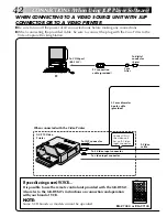
Страница 42: ...dit using a non JVC VCR It is possible to use the remote control unit provided with the GR DVM1 Also refer to the GR DVM1 s instructions on connection and operation with your brand of VCR NOTE Some VCR brands or models cannot be operated GV PT2 Video Printer When connected with the Video Printer PC To COM port RS 232C PC connection cable provided Core Filter To digital connector 8 pin 3 5 mm diame...

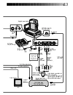
Страница 43: ...nput jack To AUDIO input jacks L R To VIDEO input jack To DC output jack Core Filter To S Video output jack To video output jack Video cable Connect to TV To remote pause jack VIDEO OUT select switch Y C or CVBS TV Connect to TV Connect to AV jack equipped TV or to VCR JVC Video unit Recording deck Connect this if the video unit has an S input jack EDIT cable provided Cable adapter provided only w...

Страница 44: ...ission port compatible with 9600 bps transmission rate conneclable to RS 232C with 9 pin serial connector Recommended compatible with UART 16550A Mouse WindowsT compatible CD ROM drive Note An optional 9 pin serial conversion adapter is required for computers using serial communication port other than standard 9 pin MicrosoftT and WindowsT are either registered trademarks or trademarks of Microsof...

Страница 45: ...tup was completed successfully appears 5 Click OK to complete installation WINDOWST 3 1 Refer to the WindowsT 3 1 manual of or your computer manual for details on basic WindowsT 3 1 operating procedures Installation Procedure This software offers you the choise of viewing on screen messages in English or French Select the desired language during installa tion by performing the following steps To s...

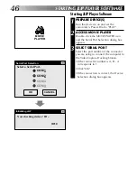
Страница 46: ...he device s on and set the camcorder s Power Dial to PLAY 2 ACCESS MOVIE PLAYER Double click the MOVIE PLAYER icon and the Serial Port Selection dialog box appears 3 SELECT SERIAL PORT Select the port number of the connector you are using to connect the computer to the Video Capture Docking Station If the connector number is A B A corresponds to 1 Click OK If the connection is correct the Device S...

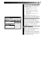
Страница 47: ...rial COM ports are occupied by other applications the error message Error This application will close Check devices Confirm that power is ON appears Free a serial COM port to start up JLIP Player Software 4 SELECT DEVICE S Click on the name of the device you wish to control Clicking OK brings up the MOVIE PLAYER window It is possible to select a second device of a different type simultaneously but...

Страница 48: ...00 00 00 00F 06 File Video Printer Help Edit MOVIE PLAYER WINDOW BUTTONS AND DISPLAYS 5 POWER button Control menu box Menu bar 1 COUNTER system 2 Tape counter display 3 ID number Icon button 4 FILE name 6 MEMO 11 MODE display 8 START button 12 SCENE button 13 IN OUT point button 9 ELAPSED TIME 7 IN OUT point display 14 Message display Title bar 10 Camcorder s operation buttons ...

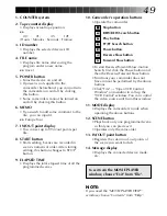
Страница 49: ...apsed time of all the programmed scenes 10 Camcorder s operation buttons Operate the camcorder To start Reverse Forward Slow motion Search first click the Pause button and then the Reverse Forward Slow button Functions your camcorder does not have cannot be performed by the above buttons Click File Open VCR Control Window on menubar to call up the VCR Control window You can control the video sourc...

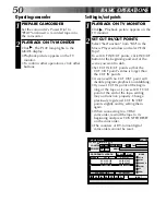
Страница 50: ...sly registered CUT IN OUT points slightly and try setting them again When connecting to a VHS C camcorder rewind the tape to its beginning and press COUNTER RESET on the camcorder The counters of DV format digital camcorders cannot be reset Operating camcorder 1 PREPARE CAMCORDER Set the camcorder s Power Dial to PLAY and insert a recorded tape into the camcorder 2 PLAYBACK ON TV MONITOR Click The...

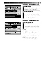
Страница 51: ...PLAYBACK Click SCENE The camcorder searches the scene by going to a point prior to the CUT IN point and starts playback at the CUT IN point Playback stops after the CUT OUT point is passed MOVIE PLAYER FILE POWER PROGRAM PLAYBACK COUNTER Non Drop MEMO ID SCENE CUT IN CUT OUT STOP SCENE ELAPSED TIME ÀÀÀ 00 10 04 28F IN OUT OFF ON MODE STILL PLAY SEARCH SLOW FF REW 00 01 25 17F 06 01 02 03 00 01 30 ...

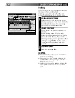
Страница 52: ...ring dubbing do no operation other than pressing STOP If other opera tions are done a malfunction may occur 3 STOP EDITING Stop the recording deck NOTES Also refer to the camcorder s instruction manual on dubbing There may be small margin between the CUT IN OUT points you input and the dubbed scenes ones Dubbing is impossible using a camcorder whose JLIP connector serves as an Edit jack MOVIE PLAY...

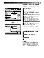
Страница 53: ...FLOPPY DISK DRIVE Click Ä in DRIVE 2 OPEN SUBDIRECTORY Click tape in the DIRECTORY 3 SAVE FILE Click OK NOTE If the MOVIE PLAYER window is closed before saving the file the file will not be saved So save the file before closing the MOVIE PLAYER window if you wish to keep it MOVIE PLAYER FILE POWER PROGRAM PLAYBACK COUNTER Drop MEMO ID SCENE CUT IN CUT OUT START SCENE ELAPSED TIME 00 10 04 28F IN O...

Страница 54: ...ppear in the FILE NAME field Click on the file name you want and it appears in the field above 3 DETERMINE FILE NAME Click OK and the file will be read The MOVIE PLAYER window returns Open a program list FILE NAME MEMO DIRECTORY travel jlp CANCEL OK DRIVE c travel jlp c jlip tape Europe Tour Correcting the program counter data 1 DESIGNATE SCENE Double click on the scene you want to modify OR Click...

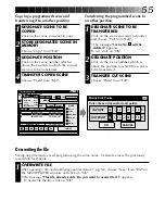
Страница 55: ...verwrite it appears To overwrite the file click on OK MOVIE PLAYER FILE POWER PROGRAM PLAYBACK COUNTER Drop MEMO ID SCENE CUT IN CUT OUT START SCENE ELAPSED TIME 00 13 08 12F IN OUT OFF ON MODE STILL PLAY SEARCH SLOW FF REW 00 27 10 21F 06 File Video Printer Help Edit Modify Cut All Clear Copy Paste Set Function Ctrl E Ctrl X Del Ctrl C Ctrl V Edit 00 05 55 12F 00 12 10 12F 00 23 22 10F 00 10 37 1...

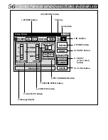
Страница 56: ...SE STROBE SPEED HIGH LOW À À 16 4 OFF STROBE SELECTED SAME MULTI PIX CONTENT Aperture Off OFF ON Title bar 9 STORE button 10 PRINT button 11 SELECT scene select button 12 CLOSE button 1 POWER button 2 POSITION button 3 ID number 8 PIX STABILIZER button 7 STROBE SPEED button 6 CONTENT button 5 MULTI PIX button 4 Message display Icon button ...

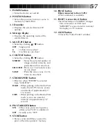
Страница 57: ...ne 4 or 16 times on one sheet 7 STROBE SPEED button Effective when STROBE is selected from CONTENT HIGH When printing in the Strobe Print mode the GV PT2 stores scenes at intervals of approximately 1 15 second LOW When printing in the Strobe Print mode scenes are stored at intervals of approximately 1 2 second 8 PIX STABILIZER button ON If the scene you want to print is jittery select ON to stabil...

Страница 58: ...The selected scene is stored in memory and appears on the TV monitor 4 PRINT Insert print paper into the video printer and click PRINT Also refer to the video printer s instruction manual The following print styles are also available Printing the same scene 4 or 16 times on one sheet Multi Print Printing various scenes on the same print sheet Multi Print Printing a scene within a scene Inset Print...

Страница 59: ...59 Quitting the MOVIE PLAYER window 1 CHOOSE EXIT FROM FILE The MOVIE PLAYER window closes Quitting the Video Printer window 1 CLICK CLOSE The Video Printer window closes ...

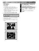
Страница 60: ...e buttons Ä Preparation Load the tape into the video unit Convert the captured data to JLIP Player software data and store it Z p 35 Select file name Z p 54 Prepare for printing refer to the GV PT2 instruction manual Select desired layout using the remote control unit provided with the GV PT2 To Print Captured Video Data with Video Printer Captured video data can be automatically scanned and print...

Страница 61: ...ext scene is automatically searched and stored in the video printer 6 Click PRINT to start printing NOTES To print only the cut in scene on the edited tape 1 Perform editing refer to pages 50 through 52 2 Print follow steps 1 through 5 above Select Auto Capture in step 4 Click START in step 5 The cut in point of Scene No 1 is automatically searched and stored in the video printer You cannot start ...

Страница 62: ...ew ID number appears 3 ENTER NEW ID NUMBER 4 SET ID NUMBER Click OK The message The device ID will be changed appears Clicking OK again sets that ID number and brings up the MOVIE PLAYER window NOTES After step 4 perform the following Connecting other device during operation Do not enter ID number 0 because JLIP Player Software does not recognize ID 0 1 INITIALIZE Choose Initialize from File on th...

Страница 63: ... Changing the device to use while connecting over two same type devices 1 ACCESS DEVICE SELECTION DIALOG BOX Choose Device Change from File on the MOVIE PLAYER window The Device Selection dialog box appears 2 SELECT DEVICE Click on the name of the device and OK NOTE It is impossible to use two same type devices simultaneously When Using the Video Capture Software The JLIP Player Software and JLIP ...

Страница 64: ...OFF ON MODE STILL PLAY SEARCH SLOW FF REW 00 00 01 20F 06 01 02 03 00 01 30 12F 00 07 15 21F 00 15 50 11F 00 03 27 14F 00 10 40 18F 00 20 33 10F File Video Printer Help Edit travel Europe Tour New Open Save Save As ID Change Device Change Name Change Pause Time Open VCR Control Window Close Serial Initialize Counter Reset Exit Ctrl N Ctrl O Ctrl S Ctrl A File Pause Time Correction OK CANCEL Type i...

Страница 65: ... 42 43 m If device was turned off and on again during operation click OK All devices should function properly v The line where the name of the device to use appears is not clicked m Click on it and OK Z pg 47 v The video cassette is not loaded in the camcorder When the video cassette is removed during operation this message appears m Insert the video cassette into the camcorder v The value of the ...

Страница 66: ...put connector Audio Output 8 dB 1 kiloohm pin jack JLIP x 2 3 5 mm dia 4 pole mini head jack compatible with EIAJ RC 5325 plug Digital Mini DIN 8 pin Multi connector 34 pin Editing connector 3 5 mm dia 2 pole DC output 5 V DC Captured image sizes 768 x 552 pixels 80 x 60 pixels Operating temperatures 5 to 30 C Dimensions 113W x 61H x 145D mm Weight Approx 395 g Power supply 6 3 V DC E O E Design a...

Страница 67: ...re Z pg 21 30 Full image data Z pg 21 H Help Menu Z pg 23 49 I Index image Z pg 21 26 28 Index image data Z pg 21 Initialize Z pg 17 46 Input button Z pg 20 Install Z pg 15 45 Interval Capture Z pg 28 IRQ Z pg 37 J JPEG Z pg 30 M Main Window Z pg 20 Memory button Z pg 20 Menu bar Z pg 20 48 O Open Index Z pg 33 Open JLIP jlp File Z pg 34 Operate VCR Z pg 23 49 P Picture Format Z pg 30 Program Capt...

Страница 68: ...GV DS1 COPYRIGHT 1997 VICTOR COMPANY OF JAPAN LTD EK EA Printed in Japan 0397MKV UN VP VICTOR COMPANY OF JAPAN LIMITED ...

Отзывы: