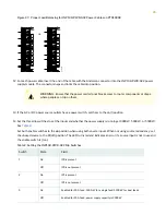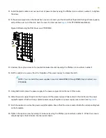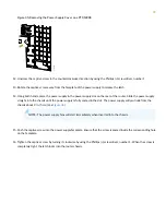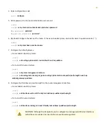
Set both enable switches to the | (on) position when using both source inputs. When not using source redundancy, set
the unused source to the off (O) position. The LED turns red and indicates an error if a source input is not in use and
the enable switch is on (|).
Figure 32: Setting the Enable Switches for the Power Source
2
—
1
—
Power switch, on (|) and standby (o)
Dip switches for enabling input sources
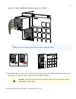
21. Verify that the input 1 and 2 LEDs on the power supply faceplate are lit and are on steadily.
22. Press the power switch to the on (|) position.
Install Dual DC Power Supplies (JNP10K-PWR-DC2)
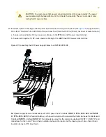
The JNP10K-PWR-DC2 power supply provides two power supplies in a single housing that accepts either 60 A or 80 A
using four redundant input power feeds. PS_0 and PS_1 each have redundant input feeds: A0 and/or B0 for PS_0 and A1
and/or B1 for PS_1. The input is configured using a set of dip switches on the power supply faceplate. The output is
dependant on the settings of these dip switches.
Before you install an JNP10K-PWR-DC2 power supply in the chassis, ensure that you have followed all safety warnings
and cautions:
WARNING:
Before performing DC power procedures, ensure that power is removed from the DC
circuit. To ensure that all power is off, locate the circuit breaker on the panel board that services the
DC circuit, switch the circuit breaker to the off (O) position, and tape the switch handle of the circuit
breaker in the off position.
35

