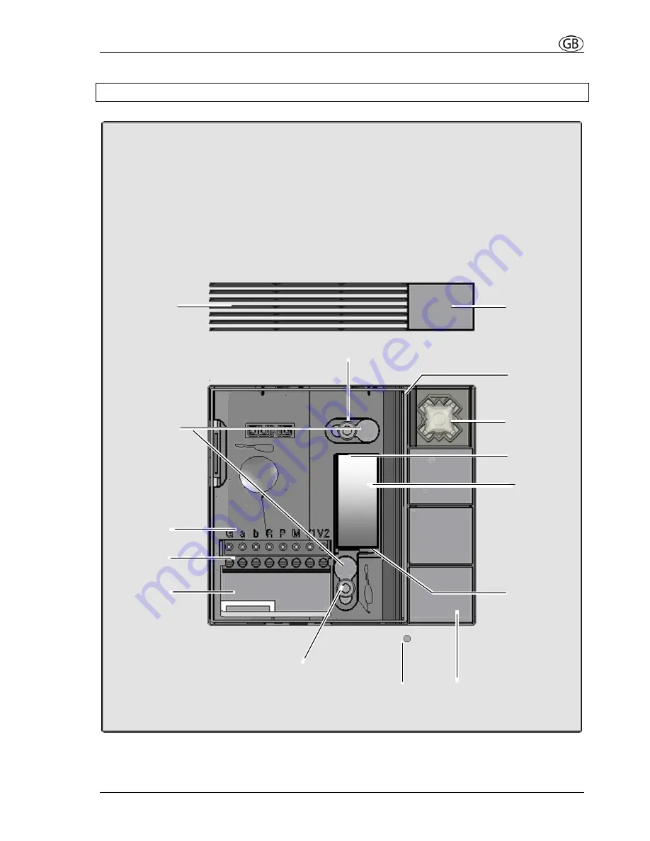
Jung TK AS AL 114 Скачать руководство пользователя страница 5


Device overview 


Fig: TK AS AL 114, without inscription plate


Screw 

Screw 

Terminals 


Pluggable 
EEPROM-
board 

DIP 
switch 

Loudspeaker 

Mounting hole 


Bell button 

Cable entry 

Microphone hole 

Light sensor 

Terminal 
description 

Faceplate 

Inscription  
plate  
illumination 

Cover 

Plug-in  
position for 
bell button 


Содержание TK AS AL 114

Страница 1: ...4 gang TK AS AL 114 WW TK AS AL 114 TK AS ES 114 2 to 8 gang TK AS AL 128 WW TK AS AL 128 TK AS ES 128 ALBRECHT JUNG GMBH CO KG Volmestra e 1 58579 Schalksm hle Phone 49 2355 806 0 Fax 49 2355 806 189...

Страница 2: ...Programming a second indoor station to a bell button parallel call 16 Deleting the programming 17 Parameters 18 Settable parameters 18 Setting and blocking OS address 18 Setting and cancelling a prog...

Страница 3: ...0 must be observed separate cabling for high and low voltage lines minimum distance of 10 cm for joint cabling arrangements use of separators between high and low voltage lines in joint cable ducts us...

Страница 4: ...ton acoustic status indication if system is occupied existing communication automatic call cut off durable energy saving LEDs for labelling illumination fault analysis due to different flashing of the...

Страница 5: ...iption plate Screw Screw Terminals Pluggable EEPROM board DIP switch Loudspeaker Mounting hole Bell button Cable entry Microphone hole Light sensor Terminal description Faceplate Inscription plate ill...

Страница 6: ...Wiring example 2 wire technique Please observe cable length and loop resistance Indoor station Indoor station Outdoor station Power supply control unit Floor bell button Floor bell button Door releas...

Страница 7: ...relay TK TR 24 EB Floating relay contact Max AC 24 V 2 A of external power supply 3 wire technique Please observe cable length and loop resistance Indoor station Indoor station Outdoor station Power s...

Страница 8: ...Attach with plaster by means of using plaster straps 4 metal sheets with holes 4 screws and 4 nuts These plaster straps can be connected on the reverse side of the housing to the housing straps 3 Flu...

Страница 9: ...screw 1 after this the lower screw 2 Connect the wires Take off the connection block downwards Attach the wires to the connection block in accordance with the terminal description Plug on the connecti...

Страница 10: ...nscription field 2 inscription foil 3 gasket Close the opening with the gasket 3 Pay attention of the gasket position Closing the device Put the nameplate with the upper edge into the housing and snap...

Страница 11: ...ght switching Acoustic and optical signals pressing buttons Positive acknowledge tone Negative acknowledge tone button already programmed Ring tone from programming acknowledgement Nameplate illuminat...

Страница 12: ...n layout is changed all of the bell buttons have to be deleted All bell buttons are assigned with the light switching function DIP switch cover Open the device if necessary Remove the cover over the D...

Страница 13: ...n layout To activate the new button layout the buttons must be programmed as bell buttons as signment of an indoor station If a 2 gang or 1 gang button is to be used as a light button this button must...

Страница 14: ...the LED on the power supply and control unit is illuminated The button layout must be set before the bell buttons are programmed The programming must be deleted before a previously programmed bell but...

Страница 15: ...utdoor station and a ring tone sounds at the indoor station 1 Repeat steps until all bell buttons have been programmed 3 Finishing press briefly LED lights up Outdoor station in idle mode Programming...

Страница 16: ...ial numbers and then reprogram both serial numbers again 1 Initiation press briefly LED flashes Outdoor station in programming mode flashes programming mode of the system is switched on 2a By means of...

Страница 17: ...gramming has to be deleted 1 Initiation press briefly LED flashes Outdoor station in programming mode flashes programming mode of the system is switched on 2 Execution if bell button programmed 6s if...

Страница 18: ...At the same time when the programming block is cancelled the light switching function and talking only after incoming door call are cancelled and the acknowledge tone is reset to the factory pre setti...

Страница 19: ...e Set switch 8 to ON Nameplate illumination flashes quickly 0 125 s On 0 125 s Off 4 Apply parameter Pressing any bell button saves the desired value for the parameter being set An acknowledge tone so...

Страница 20: ...F OFF ON OFF OFF 1 1 1s 30s OFF ON OFF 2 2 2s 45s 2 2 ON ON OFF 3 3 3s 60s 3 3 OFF OFF ON 4 4 4s 75s 4 4 ON OFF ON 5 5 5s 90s 5 5 OFF ON ON 6 6 6s 105s Parameter value ON ON ON MAX MAX 7s 135s ON ON 7...

Страница 21: ...f No TK 60 FO Fault identification indication and querying Faults are signalled visually and acoustically single fault tone and continuous flashing of the light strip The fault type can be queried by...

Страница 22: ...n of the outdoor station will switch the light if the bell button is not assigned to an indoor station Light switching function Programming at the pow er supply and control unit This door release butt...

Страница 23: ...station to the same indoor station Each bell button can be assigned to a separate ring tone e g individual ring tones for each family member Automatic door release The door release relay will be acti...

Страница 24: ...y control unit than 20 Ohm Rule Turn OFF 230 V 50 Hz of the VS Connect a and b short circuit at the VS All other devices do not disturb the measuring proc ess and remain connected 20 Ohm 160 m wire le...

Страница 25: ...on humidity 0 to 80 r h Installation height Recommended 1 50 m Acceptance of guarantee We accept the guarantee in accordance with the corresponding legal provisions Please return the unit postage paid...

Отзывы: