9
Service
Please note that all service must be carried out by a qualified
person.
Adjustment of pressure switch
The working presure has ben preset from the factory, and it is
normally not necessary to change this.
However, if it is necessary to change the preset settings, the
instructions mentioned below should be followed carefully.
Warning!
The compressor is constructed and approved
for a max. pressure as stated under Technical
Specifications - do not adjust to a higher pressure.
Higher working pressure will reduce the lifetime of
the compressor.
The compressor will stop at max. pressure (stop pressure) and
start again at min. pressure (start pressure). The difference
between max. and min. pressure is the differens pressure.
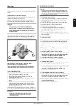
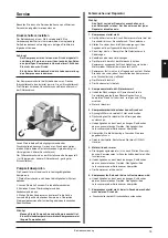
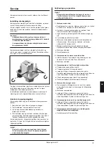
Unscrew the lid of the pressure switch. Adjust max. pressure
adjusting the two springs marked A (clockwise: higher
pressure). Adjust the two springs identically.
Adjust the differens pressure adjusting the spring marked B
(clockwise: higher differens pressure, lower start pressure.
Test of pumping time
The pumping time indicates the condition of the compressor.
Check that there are no leaks in the system.
Empty the air receiver of compressed air so that the
pressure gauge shows 0 bar.
Close the filter regulator and check that the drain valve is
closed.
Start the compressor and note the time it takes until it is
turned off again by the pressure switch. Check that the
pumping time agrees with the technical specifications for
the actual compressor system.
Please note that the pumping time in this manual is given for 0
to max pressure. Deviations from this result in deviating results.
Important!
Always test the pumping time when cold. If the
compressor is warm, the pumping time will be
considerably longer.
1.
2.
.
4.
Fault finding and repair
Important
Switch off and isolate from electrical supply before
removing any parts from the compressor. Empty air
receiver of air before performing any operation on the
compressors' pressure system.
1. Compressor does not start
The air receiver is pressurized. The motor will start when
the pressure has dropped to the preset start pressure.
Empty the receiver.
Check that the mains supply agrees with the motor label.
No power from mains. Check fuses and plug.
Bad connection or broken cable.
The motor is overheated and the thermal protection
has switched it off. When cooled the motor will turn on
automatically. Go to section 5.
The compressor has not been unloaded and there is back
pressure on the piston. Ensure that the compressor is unloaded
each time it stops.
The motor is blocked.
Defective capacitor.
2. The compressor makes a buzzing sound but does not start
Leaky non-return valve. Dismount the pressure pipe and
check if air leaks from the non-return valve. Clean and
replace.
The motor is blocked.
3. The compressor runs but the pressure does not increase
Intake filter clogged. Replace.
Non-return valve is clocked. Clean or replace.
Leaks in fittings, tubes or pneumatic equipment. Check with
soapy water or by letting unit stay over night disconnected
from mains. Pressure drop should not exceed 1 bar.
Check the piston gaskets. Replace if necessary.
Defective valve plate. Contact your JUN-AIR distributor.
5. The motor gets very hot
The ambient temperature is too high. If the motor is installed
in a cabinet sufficient ventilation must be ensured.
Leaks in fittings, tubes or pneumatic equipment. Check with
soapy water or by letting unit stay over night disconnected
from mains. Pressure drop should not exceed 1 bar.
The compressor is overloaded.
6. The compressor runs even if no air is tapped
Leaks in fittings, tubes or pneumatic equipment. Check with
soapy water or by letting unit stay over night disconnected
from mains. Pressure drop should not exceed 1 bar.
7. The compressor does not start at min pressure or does
not stop at max pressure.
Defective pressure switch. Replace.
a.
b.
c.
d.
e.
f.
g.
h.
a.
b.
a.
b.
c.
d.
e.
a.
b.
c.
a.
a.
B
A
+
-
+
-
Operating manual
GB
Содержание 2 OF302-40M Series
Страница 4: ......
Страница 30: ...30 6072960 Electrical diagram OF301 and 302 M D Diagrams...
Страница 31: ...31 6073160 Electrical diagram 2xOF301 and 2x302 M D Diagrams...
Страница 32: ...32 Electrical diagram 3x302 M D 6073250 Diagrams...
Страница 36: ...36 Spare parts motor OF301 0070000 0080000 Spare parts motor OF302 Spare parts...
Страница 37: ...37 Spare parts OF301 4M 0080120 Spare parts...
Страница 38: ...38 Spare parts OF301 4MD2 0080121 Spare parts...
Страница 39: ...39 Spare parts OF302 4M 0080122 Spare parts...
Страница 40: ...40 Spare parts OF302 4MD2 0080123 Spare parts...
Страница 41: ...41 Spare parts OF302 25M 0080130 Spare parts...
Страница 42: ...42 Spare parts OF302 25MD2 0080131 Spare parts...
Страница 43: ...43 Spare parts 2xOF302 40M 0080140 Spare parts...
Страница 44: ...44 Spare parts 2xOF302 40MD2 0080141 Spare parts...
Страница 45: ...45 0080150 Spare parts 3xOF302 40M Spare parts...
Страница 46: ...46 0080151 Spare parts 3xOF302 40MD3 Spare parts...
Страница 47: ......


