8
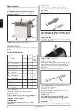
d) Clean the unit
Clean the unit when needed with a soft, damp cloth. If
necessary, use paraffin to remove adhesions. Dust and dirt
prevent cooling.
e) Check the safety valve
1
2
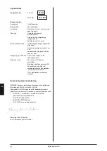
Check the safety valve with pressure in the receiver. The safety
valve is operated by pulling the ring (1) or turning the screw (2)
depending on the valve type.
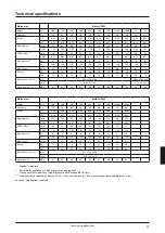
f) Check intake filter
Check the intake filter regularly. Change the filter once a year or
every 2000 operation hours.
Dismount the filter with a coin e.g.
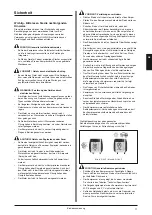
g) Check the non-return valve
Turn off the compressor on the mains switch and pull out the plug.
Empty the receiver for compressed air by operating the safety
valve. When the receiver is empty, the reading of the pressure
gauge is 0 bar.
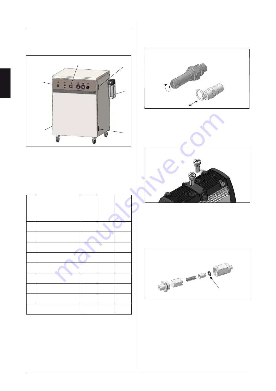
Dismount the non-return valve from the receiver.
1
Disassemble the non-return valve and remove the O-ring (1)
part no. 24000 from the piston.
Clean the non-return valve.
Mount a new O-ring and re-assemble the non-return valve.
Re-install the non-return valve.
h) Check the fans
Check that the fans at the back of the cabinet work. They
will start when the temperature exceeds 0°C and will run
continuously until the temperature falls below 0°C.
i) Check dryer
If a dryer is installed refer to the operating manual for the dryer.
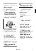
Maintenance
To ensure a long lifetime of the compressor, it is important
that inspection and maintenance is carried out regularly as
described in the following.
Read the elapsed operation time on the hour counter.
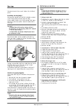
Opening of cabinet
Turn the 4 locks clockwise with a screwdriver or sim. to open the
cabinet.
Preventive maintenance
Activity
Weekly
Monthly
Once a
year or
every
2000 h
a
Drain condensate
•
b
Check filter regulator
•
c
Check for leaks
•
d
Clean the unit
•
e
Check safety valve
•
f
Check inlet filter
•
g
Check non-return valve
•
h
Check fans
•
i
Check dryer
•
a) Drain condensate
If drain bottle is installed, empty when necessary. (2).
b) Check outlet filter
Check and change the filter and filter element in accordance
with the instructions in "Installation and maintenance
instructions" for the filter in question.
c) Check for leaks
Check motor, hoses and equipment for leaks. Check the
pumping time.
1
1
1
1
2
Operating manual
GB
Содержание 2 OF302-40M Series
Страница 4: ......
Страница 30: ...30 6072960 Electrical diagram OF301 and 302 M D Diagrams...
Страница 31: ...31 6073160 Electrical diagram 2xOF301 and 2x302 M D Diagrams...
Страница 32: ...32 Electrical diagram 3x302 M D 6073250 Diagrams...
Страница 36: ...36 Spare parts motor OF301 0070000 0080000 Spare parts motor OF302 Spare parts...
Страница 37: ...37 Spare parts OF301 4M 0080120 Spare parts...
Страница 38: ...38 Spare parts OF301 4MD2 0080121 Spare parts...
Страница 39: ...39 Spare parts OF302 4M 0080122 Spare parts...
Страница 40: ...40 Spare parts OF302 4MD2 0080123 Spare parts...
Страница 41: ...41 Spare parts OF302 25M 0080130 Spare parts...
Страница 42: ...42 Spare parts OF302 25MD2 0080131 Spare parts...
Страница 43: ...43 Spare parts 2xOF302 40M 0080140 Spare parts...
Страница 44: ...44 Spare parts 2xOF302 40MD2 0080141 Spare parts...
Страница 45: ...45 0080150 Spare parts 3xOF302 40M Spare parts...
Страница 46: ...46 0080151 Spare parts 3xOF302 40MD3 Spare parts...
Страница 47: ......


