background image

5

  Information

  Please note that you can find the pictures and illustrations   
   we are referring to on page 5.

Warning

·


Unless directions are followed and original spare parts 
used, physical injury or property damage may result.

·


Protect compressor against rain, moisture, frost, and dust.

·


Compressor is only suitable for installations with the nomi­
nal voltage stated on the motor plate.

·


Do not in any way block or prevent the normal functioning of 
the safety valve on the receiver. 

·


Only connect pneumatic equipment suitable for the max. 
pressure indicated.

·


Do not operate compressor at ambient temperatures 
exceeding 5°C/95°F or falling below 0°C/2°F.

·


Do not touch compressor motor during operation as there is 
a risk of burn due to high temperatures.

·


Do not direct air flow at head or body.

·


When a flammable liquid is sprayed, there may be danger of 
fire or explosion, especially in closed rooms.

·


Always keep the compressor out of reach of children.

Guarantee

Provided that the operational instructions have been carried out, 
your JUN­AIR compressor is guaranteed against faulty material 
or workmanship for 2 years. 
The air receiver is guaranteed for 5 years. 
The guarantee does not cover damage caused by violence, 
misuse, incorrect repairs or use of wrong oil and unoriginal 
spare parts. 
Costs of transportation of parts/equipment are not covered by 
the guarantee. 
JUN­AIR’s Conditions for Sale and Delivery will generally apply. 
JUN­AIR International A/S reserves the right to change 
technical specifications/ constructions.

How to operate the JUN-AIR compressor

Your JUN­AIR compressor is very easy to operate. Observe 
the following simple instructions and you will get many years’ 
service from your compressor.
1.  Visually inspect unit for shipping damage, contact your 

supplier immediately if you think the unit may have been 
damaged.

2.  Always keep the compressor in a vertical position during 

use and transportation.

.  Place the compressor in a dustfree, dry and cool, yet 

frostfree, room. Do not install in a closed cupboard, unless 
adequate openings for ventilation are available (fig. 1). 
Ensure that the compressor stands firmly on the floor.

4.  Replace the cap on the air intake tube with the intake filter 

(fig. 2).

5.  Connect pneumatic equipment.

Important!                                                                      

The compressor oil may be aggressive towards 
certain gasket materials used in pneumatic 
equipment. We recommend Teflon, Viton, etc.. Do not 
use polycarbonate filter bowls. Contact your local 
JUN-AIR distributor if you need further information.

6.  Plug the compressor into an outlet switch of nominal voltage 

and ensure that fusing is adequate (see Technical Details).

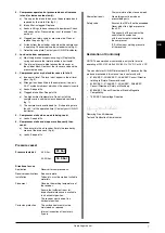
7.  Start the compressor using the 0/1 switch on the pressure 

switch (fig. ). The compressor will automatically switch off 
at the preset pressure. If the motor does not start it may 
be due to pressure in the receiver, and the motor will then 
start automatically when the pressure reduces to approx. 6 
bar/87 psi.

8.  Always keep the compressor in a vertical position as oil 

may run out of the intake filter. During transportation, mount 
the cap on the inlet. Mechanical noise from the compressor 
in connection with handling does not have any functional 
importance.

Warning! 

Never mount the transportation cap on oil-lubricated 
compressors while there is still pressure in the 
compressor & pressure vessel, as this may cause a 
pressure build up in the motor housing.

9.  Adjustment of pressure (fig. 4):
 

A:  Max. pressure adjustment (cut­out) 
B:  Differential adjustment (cut­in)


The cut­in pressure (normally 6 bar) is set by adjustment 
of differential screw B. Turn clockwise to reduce cut­in 
pressure.


The cut­out pressure is set by even adjustment of the two 
screws A. (Cut­in pr differential = cut­out pressure). 
Turn clockwise to increase cut­out pressure. 


The switch is normally factory set for operation at 6­8 bar 
(approx. 90­120 psi).

10.  Adjustment of CONDOR 4­16 press­switch (fig. 4a)
 

The cut­out pressure (normally 16 bar) is set by adjustment 
of maximum pressure screw. (Cut­in pr different 
pressure = cut­out pressure). Turn clockwise to increase 
cut­out pressure.


The cut­in pressure (normally 14 bar) is set by adjustment 
of differential screw. Turn clockwise to reduce cut­in 
pressure.


The switch is normally from the factory set for operation at 
14­16 bar. 

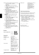
Technical details

The max. operation of the compressor is 50% of the operation 
time, and the max. operation time is 15 min. at 8 bar/120 psi in 
each cycle. Consequently, 15 min. standstill is required before 
the next start. For tables with technical data and performance 
curves, see page 2.

Operating manual

Operating manual

GB

Содержание 12-25

Страница 1: ...Operating manual Bruksanvisning Istruzioni di servizio Manual de utiliza o Instrukcja obs ugi Compressor Model 3 motor 3 4 6 motor 6 4 6 15 6 25 12 25 12 40 18 40 24 40 36 150...

Страница 2: ......

Страница 3: ...cnici 23 Dados t cnicos 23 23 Dane techniczne 23 Spare parts 30 Reservdelslista 30 Pezzi di ricambio 30 Pe as de reposi o 30 30 Cz ci zamienne 30 Drawings 33 Ritningar 33 Disegni 33 Diagramas 33 33 Sc...

Страница 4: ......

Страница 5: ...he intake filter fig 2 5 Connect pneumatic equipment Important The compressor oil may be aggressive towards certain gasket materials used in pneumatic equipment We recommend Teflon Viton etc Do not us...

Страница 6: ...types of oil may cause serious mechanical damage to the compressor Consequently the warranty only applies if SJ 27 oil is used Check the pumping time The pumping time indicates the condition of the c...

Страница 7: ...s and stops more frequently than usual a Condensate in the air receiver Empty the receiver by means of the drain cock fig 6 b Leaks See point 2c Pressure vessel Pressure tested at 4 25 liter 40 50 lit...

Страница 8: ...t plan 3 Placera kompressorn i ett dammfritt torrt och svalt men dock frostfritt rum Den f r ej placeras i ett st ngt sk p om det ej finns riktiga ventilations ppningar fig 1 4 Ers tt skyddshatten p i...

Страница 9: ...sa omst ndigheter g ller ej garantin Kontrollera pumpningstiden Pumpningstiden kan ge en indikation p kompressorns tillst nd under f ruts ttning att det ej r l ckage i anl ggningen d r tryckluften kan...

Страница 10: ...kranen fig 6 b L ckage Se punkt 2c Beh llare Beh llare tryckprovad vid 4 25 liter 40 50 liter Bruksanvisning Anv ndning Tryckluftsbeh llare Beh llarspecifikationer Se m rkskylt Installation Slangar m...

Страница 11: ...ompressore in un locale secco e fresco al riparo dall umidit dalla polvere e dal gelo Non collocarlo in un armadio chiuso a meno che orifizi di ventilazione sufficenti siano previsti fig 1 Mettere il...

Страница 12: ...un tempo di marcia abbastanza corto se si usa dell olio diverso dell olio SJ 27 raccommandato In questo caso la garanzia viene annullata Verificazione del tempo di pompaggio Il tempo di pompaggio pu...

Страница 13: ...a 4 25 litri 40 50 litri Come va operato lo serbatoio Utilizzo Serbatoio per aria compressa Dati tecnici Vedasi piastra d identificazione Istallazione Controllare la temperatura d operazione Mettere...

Страница 14: ...lquer irregularidade comunique imediatamente o seu distribuidor JUN AIR 2 Durante o transporte e utiliza o o compressor dever estar sempre nivelado 3 Instale o compressor em um local livre de p ventil...

Страница 15: ...a D a ele o destino previsto pela autoridade ambiental local 3 Volte o motor posi o vertical e reabaste a com aproximadamente 750ml de SJ 27 fig 8 4 Recoloque a tampa substituindo o anel de veda o 5 T...

Страница 16: ...o O n vel deve estar vis vel no visor entre as linhas indicadas fig 5 b O leo utilizado n o o SJ 27 Utilize exclusivamente o lubrificante original c Vazamentos nas conex es ou no equipamento pneum tic...

Страница 17: ...17 53 35 C 95 F 0 C 32 F JUN AIR 2 5 JUN AIR JUN AIR International A S JUN AIR 1 2 3 1 4 2 5 I JUN AIR 6 7 0 1 3 6 87 psi 8 9 4 A B 6 B A 6 8 90 120 psi 50 15 8 120 psi 15 23 RU...

Страница 18: ...18 max min SJ 27 5 2 6 10 7 1 4 8 2 8 3 SJ 27 0 75 8 4 5 SJ 27 SJ 27 1 0 2 3 8 1 a b c JUN AIR d e 4 f g 9 RU...

Страница 19: ...JUN AIR 5 a 2c 6 a 6 b 2c 4 25 24 40 50 18 3 5 230 V 50 Hz 3x400 V 50 Hz 12 V DC or 24 V DC JUN AIR International A S 87 404 EEC 90 488 EEC 93 68 EEC 89 392 EEC 91 368 EEC 93 44 EEC 93 68 EEC 89 336 E...

Страница 20: ...otowym rys 2 5 Pod cz instalacj pneumatyczn Uwaga Olej stosowany w kompresorach JUN AIR mo e spowodowa uszkodzenia uszczelnie wykonanych z niekt rych materia w Zalecamy stosowanie uszczelnie wykonanyc...

Страница 21: ...o ci 5 Za pokryw upewniaj c si e o ring szczelnie dolega do kraw dzi dolnej cz ci obudowy WA NE Zawsze u ywaj oleju SJ 27 u ycie oleju innego typu mo e spowodowa powa ne uszkodzenia mechaniczne spr ar...

Страница 22: ...pr arka uruchamia si i wy cza cz ciej ni zwykle a Kondensat w zbiorniku spr onego powietrza Opr nij zbiornik otwieraj c zaw r drena owy rys 6 b Nieszczelna instalacja Zobacz punkt 2c Zbiornik ci nieni...

Страница 23: ...1 1 1 1 1 1 Weight kg 18 18 18 18 18 18 18 lbs 40 40 40 40 40 40 40 Dimensions mm 384 x 333 x 342 l x w x h inch 15 1 8 x 13 1 8 x 13 4 8 Noise level dB A 1m 35 35 35 35 35 35 35 Pumping time 0 8 bar...

Страница 24: ...1 Dimensions mm 280 x 190 x 240 l x w x h inch 11 x 7 4 8 x 9 4 8 Noise level dB A 1m 45 45 45 45 45 45 45 Model 6 4 Voltage V 100 100 120 200 200 230 230 Frequency Hz 50 60 60 50 60 50 60 Motor HP 0...

Страница 25: ...ions mm 378 x 378 x 485 l x w x h inch 14 7 8 x 14 7 8 x 19 1 8 Noise level dB A 1m 45 45 45 45 45 45 45 Pumping time 0 8 bar 0 120 psi sec 220 185 185 220 185 220 185 Model 6 25 Voltage V 100 100 120...

Страница 26: ...x w x h mm 425 x 275 x 595 inch 16 6 8 x 10 7 8 x 23 3 8 Noise level dB A 1m 48 48 48 48 48 48 48 Pumping time 0 8 bar 0 120 psi sec 185 155 155 185 155 185 155 Model 12 40 Voltage V 100 100 120 200...

Страница 27: ...ar 0 120 psi sec 185 185 150 185 150 Model 24 40 Voltage V 200 200 230 230 3 200 3 200 3 208 3 4002 3 4002 Frequency Hz 50 60 50 60 50 60 60 50 60 Motor HP 1 84 1 84 1 84 1 84 1 84 1 84 1 84 1 84 1 84...

Страница 28: ...vailable upon request H here Druck lieferbar Pression sup rieure sur demande Presi n mayour sobre demanda Hogere druk op aanvraag H jere tryk kan leveres Neutral is required Null leiter ist erforderli...

Страница 29: ...min 2 0 1 5 1 0 cu ft min 0 20 40 60 80 100 120 psig 50 Hz 60 Hz Model 6 240 140 1 2 3 0 4 5 6 7 8 bar Ltr min 8 0 7 0 5 0 cu ft min 0 20 40 60 80 100 120 psi 6 0 220 200 180 160 50 Hz 60 Hz Model 24...

Страница 30: ...pipe f 6 motor 4550000 Copper washer f 6 motor 4551000 Suspension spring f 6 motor 4555000 Cylinder head f 6 motor 4556000 Bolt f cylinder head f 6 motor 4560100 Casing bottom f 3 motor 230V silver n...

Страница 31: ...ex hose 1 8 80 82 cm 6463700 Flex hose 1 8 110 112 cm 6960500 Spacer 17 mm 6961000 Spacer 23 3 mm 11x1 mm 6961200 Spacer 27 mm 6961500 Spacer f transportation tap 4 motor 6973080 Unloader valve w 16 4...

Страница 32: ......

Страница 33: ...33 Motor spare parts model 3 Motor spare parts model 3 Drawings 0013101 0013001 Drawings...

Страница 34: ...34 Motor spare parts model 6 Motor spare parts model 6 0015100 0015200 Drawings...

Страница 35: ...35 Spare parts model 3 4 0015301 Drawings...

Страница 36: ...36 Spare parts model 6 4 0015300 Drawings...

Страница 37: ...37 Spare parts model 6 15 0015400 Drawings...

Страница 38: ...38 Spare parts model 6 25 0015450 Drawings...

Страница 39: ...39 Spare parts model 12 25 0019700 Drawings...

Страница 40: ...40 Spare parts model 12 40 0200650 Drawings...

Страница 41: ...41 Spare parts model 18 40 0200660 Drawings...

Страница 42: ...42 Spare parts model 24 40 0200670 Drawings...

Страница 43: ...43 Spare parts model 36 150 0016500 Drawings...

Страница 44: ...44 Accessories 0991041 0991040 0015900 Drawings...

Страница 45: ...45 Electrical drawing model 3 6070010 Drawings...

Страница 46: ...46 Electrical drawing model 6 6070160 Drawings...

Страница 47: ...47 Electrical drawing model 12 6070210 Drawings...

Страница 48: ...48 Electrical drawing model 18 6070260 Drawings...

Страница 49: ...49 Electrical drawing model 24 400V 50Hz 6070310 Drawings...

Страница 50: ...50 Electrical drawing model 24 230V 50 60Hz 6070311 Drawings...

Страница 51: ...51 Electrical drawing model 36 400V 50Hz 6070360 Drawings...

Страница 52: ...52 Electrical drawing model 36 230V 50Hz 6070361 Drawings...

Страница 53: ...53 Fig 1 Fig 2 Fig 3 Fig 4 Pictures illustrations Fig 5 Fig 6 Fig 7 Fig 8 Fig 9 Fig 10 Fig 4a Max pressure adjustment cut out Differential adjustment cut in Pictures illustrations...

Страница 54: ......

Страница 55: ......

Страница 56: ...151 v 06 09 2008 JUN AIR INTERNATIONAL A S A Unit of IDEX Corporation Sundsholmen 3 5 9400 N rresundby Denmark www jun air com Phone 45 96 32 36 00 Telefax 45 96 32 36 01 E mail gastgroup dk idexcorp...

Отзывы: