


ADJUSTING INSTRUCTIONS
Instructions stating direction or location, such as right, left, front or rear of the machine are given relative to
the operator's position at the machine unless otherwise noted. The handwheel rotates clockwise in
operating direction.
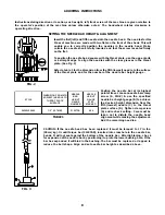
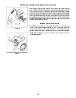
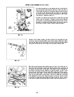
SETTING THE NEEDLE BAR HEIGHT & ALIGNMENT
Insert the first (left) and fifth needles into the needle head. The needles for this
Class of machine are made with two flats on the front of the shank This will
enable you to correctly position the needles in the needle head. Make
certain the needle shank is fully inserted and that the screw is seated firmly
on the flat.
To position the needle head square with the throat plate, use the upper knife
or a straight edge to align the needles with the cross grooves in the throat
plate. (See Fig. 2)
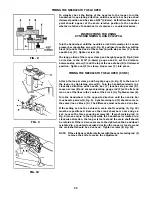
Refer to table 1 for the dimension from the fifth (lowest) needle to the surface
of the throat plate and for the number of the needle bar height gauge.
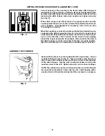
Position the needle bar at its highest
point of travel. Loosen needle bar clamp
screw (A, FIG.3) & use the specified
needle bar height gauge (B) to achieve
the desired height dimension from the
fifth (lowest) needle (C) to the throat
plate surface (D). Tighten clamp screw
(A) and recheck setting. Care must be
taken not to disturb the needle head
alignment while making the adjustment.
Add the remaining needles.
CAUTION: If the needle head has been replaced it must be torqued to 17 in. lbs.
(20cm/kg). Or until torque bar (21227AR), inserted into cross hole in the needle bar,
bends. It will not seat against the bottom of the needle bar. After tightening, check
for expansion of the needle bar by positioning it up into the lower bushing hole. If the
bar has expanded it will bind in the bushing. The bar must be replaced or lapped to
reduce the bell shape. Align and set needle bar height as described above.
FIG. 2
TABLE 1
FIG. 3
E
L
Y
T
S
H
T
5
M
O
R
F
N
O
I
S
N
E
M
I
D
O
T
E
L
D
E
E
N
)
T
S
E
W
O
L
(
E
T
A
L
P
T
A
O
R
H
T
E
C
A
F
R
U
S
E
L
D
E
E
N
R
A
B
T
H
G
I
E
H
E
G
U
A
G
R
E
B
M
U
N
E
L
D
E
E
N
T
H
G
I
E
H
E
G
U
A
G
P
E
T
S
D
E
K
R
A
M
0
6
-
0
2
2
L
0
0
2
6
3
)
M
M
7
.
2
1
(
"
2
/
1
S
D
7
2
2
1
2
0
0
5
.
8
Содержание Union Special 36200L220-60
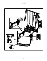
Страница 1: ...ADJUSTING INSTRUCTIONS ILLUSTRATED PARTS LIST MANUAL NO PT0204 GR FOR STYLE 36200L220 60 11 22 06...
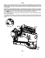
Страница 6: ...6 THREADING...
Страница 20: ...20...
Страница 22: ...22...
Страница 24: ...24...
Страница 26: ...26...
Страница 28: ...28...
Страница 30: ...30...
Страница 32: ...32...
Страница 34: ...34...
Страница 36: ...36...
Страница 38: ...38...
Страница 40: ...40...
Страница 42: ...42...
Страница 44: ...44...
Страница 46: ...46...
Страница 48: ...48...
Страница 50: ...50...
Страница 52: ...52...
Страница 56: ......


