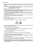
JUKI Union Special 36200L220-60 Скачать руководство пользователя страница 5

5

SAFETY RULES:

1. Before putting the machines described in this manual into service, carefully read the instructions.  The

starting of each machine is only permitted after taking notice of the instructions and by qualified
operators.

IMPORTANT!

Before putting the machine into service, also read the safety rules and
instructions from the motor supplier.

2. Observe the national safety rules valid for your country.

3. The sewing machines described in this instruction manual are prohibited from being put into service until

it has been ascertained that the sewing units which these sewing machines will be built into,  have
conformed with the EC Council Directives (89/392/EEC, Annex II B).

Each machine is only allowed to be used as foreseen.  The foreseen use of the particular machine is

described in paragraph “STYLES OF MACHINES” of this instruction manual.  Another use, going beyond

the description, is not as foreseen.

4. All safety devices must be in position when the machine is ready for work or in operation.  Operation of

the machine without the appertaining safety devices is prohibited.

5. Wear safety glasses.

6. In case of machine conversions and changes all valid safety rules must be considered.  Conversions and

changes are made at your own risk.

7. The warning hints in the instructions are marked with one of these two symbols:

8. When doing the following the machine has to be disconnected from the power supply by turning off the

main switch or by pulling out the main plug:

8.1 When  threading needle(s), looper, spreader etc.

8.2 When replacing any  parts such as needle(s), presser foot, throat plate, looper, spreader, feed dog,

needle guard, folder, fabric guide etc.

8.3 When leaving the workplace and when the workplace is unattended.

8.4 When doing maintenance work.

8.5 When using clutch motors without actuation lock, wait until the motor is stopped totally.

9.

Maintenance, repair and conversion work (see item 8) must be done only by trained technicians or

special skilled personnel under consideration of the instructions.

10. Any work on the electrical equipment must be done by an electrician or under direction and supervision

of special skilled personnel.

11. Work on parts and equipment under electrical power is not permitted.  Permissible exceptions are

described in the applicable sections of standard sheet DIN VDE 0105.

12. Before doing maintenance and repair work on the pneumatic equipment, the machine has to be

disconnected from the compressed air supply.  In case of existing residual air pressure,  after discon-
necting from compressed air supply (i.e. pneumatic equipment with air tank), the pressure has to be
removed by bleeding.

Содержание Union Special 36200L220-60

Страница 1: ...ADJUSTING INSTRUCTIONS ILLUSTRATED PARTS LIST MANUAL NO PT0204 GR FOR STYLE 36200L220 60 11 22 06...

Страница 2: ...rations and terminology used in describing the parts used on 35600 Series machines 2 CONTENTS PREFACE 2 TERMS 2 IDENTIFICATION OF MACHINES 3 TORQUE REQUIREMENTS 3 DESCRIPTION OF MACHINES 3 STYLE OF MA...

Страница 3: ...a style number which is stamped into the style plate affixed to the middle of the machine under the tension assembly The serial number is stamped in the casting at the right rear base of the machine T...

Страница 4: ...and ifnecessary the difference will be shown in the illustration A numerical index of all the parts shown in this manual is located at the back This will facilitate locating the illustration and descr...

Страница 5: ...ges are made at your own risk 7 The warning hints in the instructions are marked with one of these two symbols 8 When doing the following the machine has to be disconnected from the power supply by tu...

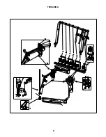
Страница 6: ...6 THREADING...

Страница 7: ...d through windows A and B When installing a new machine or starting a machine that has been idle for some time priming may be necessary Remove plug screws E fill holes with recommended oil and replace...

Страница 8: ...e bar at its highest point of travel Loosen needle bar clamp screw A FIG 3 use the specified needle bar height gauge B to achieve the desired height dimension from the fifth lowest needle C to the thr...

Страница 9: ...centered to the throat plate and cylinder however to provide clear ance on the left side of the needle for the needle loops passing around the looper during the down stroke of the needles the slots i...

Страница 10: ...sitioned to the far right Set pointer C at zero degrees by rotating gauge plate A and lock in place Continue turning the handwheel until the pointer stops If the looper travel is correct the pointer s...

Страница 11: ...ch the looper clamp and height gauge A Fig 9 to the heal of the looper by tightening screw B Turn the handwheel slowly in a clockwise direction until needle bar C touches stop screw D Loosen screw E a...

Страница 12: ...from the extended position to flush represents 094 2 4mm travel To adjust the looper avoid remove the cylinder cover and loosen screw A Fig 12 with TT 85 wrench Raise the ball joint to shorten the avo...

Страница 13: ...ntial feed dog A Fig 17 with screw B Attach rear needle guard C to main feed dog D pushing in fully to the rear and tighten screw E Install main feed dog with screw F As a starting point loosen screw...

Страница 14: ...et from numbers 1 to 4 reverse differential or stretching occurs The numbers from 4 to 5 produce equal feed stitching while numbers 5 to 9 produce a gathering stitch The two stop screws D can be set t...

Страница 15: ...Fig 22 in lifter lever link assembly B and position lever C so there is 1 32 0 8mm clearance between it and presser bar guide D when the feed dogs are below the throat plate When the hook swings to th...

Страница 16: ...of frame chip guard A Fig 26 slightly loosen screw B and turn washer C with 21388Y spanner wrench until spring D snaps the guard into the closed position Tighten screw B A light resistance should be f...

Страница 17: ...move knife in or out as required Tighten screw C securely Turn handwheel in operating direction until knife driving bracket D is positioned to the extreme left At this time the front edge of both kni...

Страница 18: ...e top of screw B Loosen screw C and turn knurled knob D to adjust the spring tension Tighten screw C Tension of the seven threads is individually controlled The needle tension is seldom uniform the fi...

Страница 19: ...e shoulder of stud B This adjustment will raise the presser foot slightly so only the pressure of the presser foot shoes contact the material Turn handwheel in operating direction until the feed dogs...

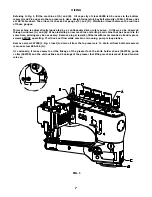
Страница 20: ...20...

Страница 21: ...Screw Cover Thread Take up Eyelet Cast Off Plate Assembly Screw for cast off Cast off Screw for cast off plate eyelets Cast off Plate Eyelet rear Cast off Plate Eyelet front Cast off Plate Cover Thre...

Страница 22: ...22...

Страница 23: ...hing front Needle Lever Shaft Bushing rear Rubber O Ring Oil Drain Screw Frame Needle Thread Eyelet Screw for needle thread eyelet Screw for unlocking spring height adjusting Stitch Unlocker Mounting...

Страница 24: ...24...

Страница 25: ...Pump Assembly Screw for housing cover Vent Screw Gasket Housing Cover and Oil Tube rear Intake Filter Pump Body and Gear Assembly Housing Cover and Oil Tube front Plug Screw Nut Screw Oil Splitter Scr...

Страница 26: ...26...

Страница 27: ...Assembly Screw Clamp Plate Handwheel Pulley Screw for adjustable pulley Ball Bearing Bushing Pump Barb Fitting Pump Assembly Tube retainer spring Tubing Tube retainer spring Oil Tube Oil Intake Felt...

Страница 28: ...28...

Страница 29: ...plunger segment pin Presser Bar Lifter Lever Screw Lifter Lever Connecting Link Presser Foot Connection Lifter Lever Retaining Ring Screw for presser foot lifter bearing bracket Presser Foot Lifter B...

Страница 30: ...30...

Страница 31: ...ew for front head cover Needle Thread Strike off Pin Screw for needle thread take up Needle Thread Take up complete Strike off Pin Holder Screw for needle thread take up Screw for needle thread take u...

Страница 32: ...32...

Страница 33: ...resser Foot Guide left Screw for left presser foot guide Washer Needle Head for 6 0 Gauge Screw for needles and retainer Screw for left head cover Head Cover left Gasket for left head cover Washer Scr...

Страница 34: ...34...

Страница 35: ...ferential Feed Bar Feed Bar Plate Screw Screw for differential feed dog Differential Feed Dog marked AAK 20 teeth per inch Screw for needle guard Needle Guard Screw for main feed dog Main Feed Dog mar...

Страница 36: ...36...

Страница 37: ...djusting Lever Differential Feed Adjusting Link Screw Differential Driving Link Stud Differential Feed Driving Link Slide Block Feed Rocker Screw Bushing Screw Feed Drive Assembly Feed Drive Eccentric...

Страница 38: ...38...

Страница 39: ...and Hook Driving Sleeve Nut Washer Screw Rod End Bearing Nut right thread Cover Thread Carrier and Hook Driving Connection Rod Ball Joint Washer Presser Bar Guide Screw Nut O Ring Torlon Washer Knife...

Страница 40: ...40...

Страница 41: ...Mounted Needle Guard marked FZ Screw for needle guard Looper Screw Looper Holder Looper Adjusting Screw Screw Screw Looper Rocker Shaft Looper Shaft Collar Screw Looper Shaft Sleeve Guide Stud Ball F...

Страница 42: ...42...

Страница 43: ...plate Edge Guide Screw for edge guide Screw for cylinder cover Screw for lap former Screw for lap former Lap Former Gib right Gib left Lap Former Slide Block Spring for lap former slide block Screw f...

Страница 44: ...44...

Страница 45: ...d Screw Gasket for bottom cover Screen for bottom cover Rubber O Ring for screen Oil Drain Plug Screw Screw for bottom cover Bottom Cover Screw for cylinder side cover Cylinder Side Cover Gasket for c...

Страница 46: ...46...

Страница 47: ...Driving Lever and Shaft Link for ref no 5 6 and 8 Cover Thread Carrier and Hook Driving Segment Presser Foot Base Screw for presser foot base Cross Thread Hook Screw for cross thread hook Spring for y...

Страница 48: ...48...

Страница 49: ...No Description Amt Req Ref No 49 THREAD STAND 1 2 3 21101S7 21233AJ 21233KS 22651CD 5 Thread Stand complete Bracket Connection marked AJ Bracket Connection marked KS Screw for bracket connection 1 1...

Страница 50: ...50...

Страница 51: ...1227BV GR 51899 Looper Travel Gauge complete Looper Travel Gauge Pointer Looper Travel Gauge Plate Wrench for driving link stud Needle Height Gauge Looper Gauge Spanner Wrench Synchronizing Gauge for...

Страница 52: ...52...

Страница 53: ...BRICATOR 1 2 3 4 5 6 7 8 J35680AZY 35893J 666 339 22585C 660 219AX 50358M 22894BL J35693K 28604W Needle Thread Lubricator Complete Reservoir Cover Reservoir Wick Screw Pin Eyelet Screw Post Reservoir...

Страница 54: ...72Y 25 29476XC 21 29476YP 33 29478CS 35 29478CT 37 29478CU 41 29478CZ 45 318 33 33174B 35 35751G 41 35761D 23 35763F 27 35763G 27 35766B 37 35767 31 35781D 23 35792 29 35792T 29 35816 27 35836C 37 358...

Страница 55: ...25 50393 260 27 50393CS 27 50393KM 27 51235G 39 51259 31 51292F 2 29 51292F 4 29 51292F 5 29 52336 41 52841H 39 52958C 21 52958F 21 531 43 45 53636C 41 538 45 60078Z 45 604 41 6042A 21 33 6042A 37 60...

Страница 56: ......

Отзывы: