


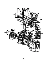


12
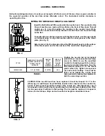
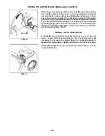
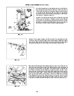
LOOPER ADJUSTMENTS
Looper Avoid
The looper avoid is set at .094" (2.4mm). Using gauge no.
21227BV (A, Fig. 11), position looper shaft (B) fully to the rear
(away from operator) and insert the gauge through the looper
shaft hole in the end of the cylinder until the plunger is fully
extended from the gauge. Tighten clamp screw (C). When the
looper is positioned fully to the front, the end of the plunger
should be flush with the end of the gauge. The motion of the
plunger from the extended position to flush represents .094"
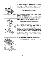
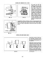
(2.4mm) travel. To adjust the looper avoid remove the cylinder
cover and loosen screw (A, Fig. 12) with TT-85 wrench. Raise the
ball joint to shorten the avoid motion or lower it to lengthen the
avoid motion. Tighten screw (A). Reposition gauge (A, Fig. 11)
and recheck the setting.
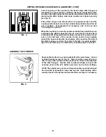
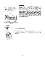
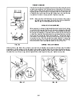
Vertical Adjustment of Looper
A clearance of .018" to .025" (0.46mm to 0.64mm) should be maintained
between the top of the looper and the bottom of the stitch tongue. Loosen
screw (C, Fig. 13) and turn screw (D), directly under the looper, up or down as
required. Make sure the looper is seated and tighten screw (C). Check for
clearance.
FIG. 11
FIG. 12
FIG. 13
Содержание Union Special 36200L220-60
Страница 1: ...ADJUSTING INSTRUCTIONS ILLUSTRATED PARTS LIST MANUAL NO PT0204 GR FOR STYLE 36200L220 60 11 22 06...
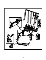
Страница 6: ...6 THREADING...
Страница 20: ...20...
Страница 22: ...22...
Страница 24: ...24...
Страница 26: ...26...
Страница 28: ...28...
Страница 30: ...30...
Страница 32: ...32...
Страница 34: ...34...
Страница 36: ...36...
Страница 38: ...38...
Страница 40: ...40...
Страница 42: ...42...
Страница 44: ...44...
Страница 46: ...46...
Страница 48: ...48...
Страница 50: ...50...
Страница 52: ...52...
Страница 56: ......


