JUKI JX-100 Скачать руководство пользователя страница 32

Operation manual


3

3.2  When components run out

 (If the check box    “Stop system when 

components run out” is not checked on the “Operation option” screen)


After the machine finishes placing all components that can be placed on boards, the 
following screen appears and the mounter stops temporarily. 
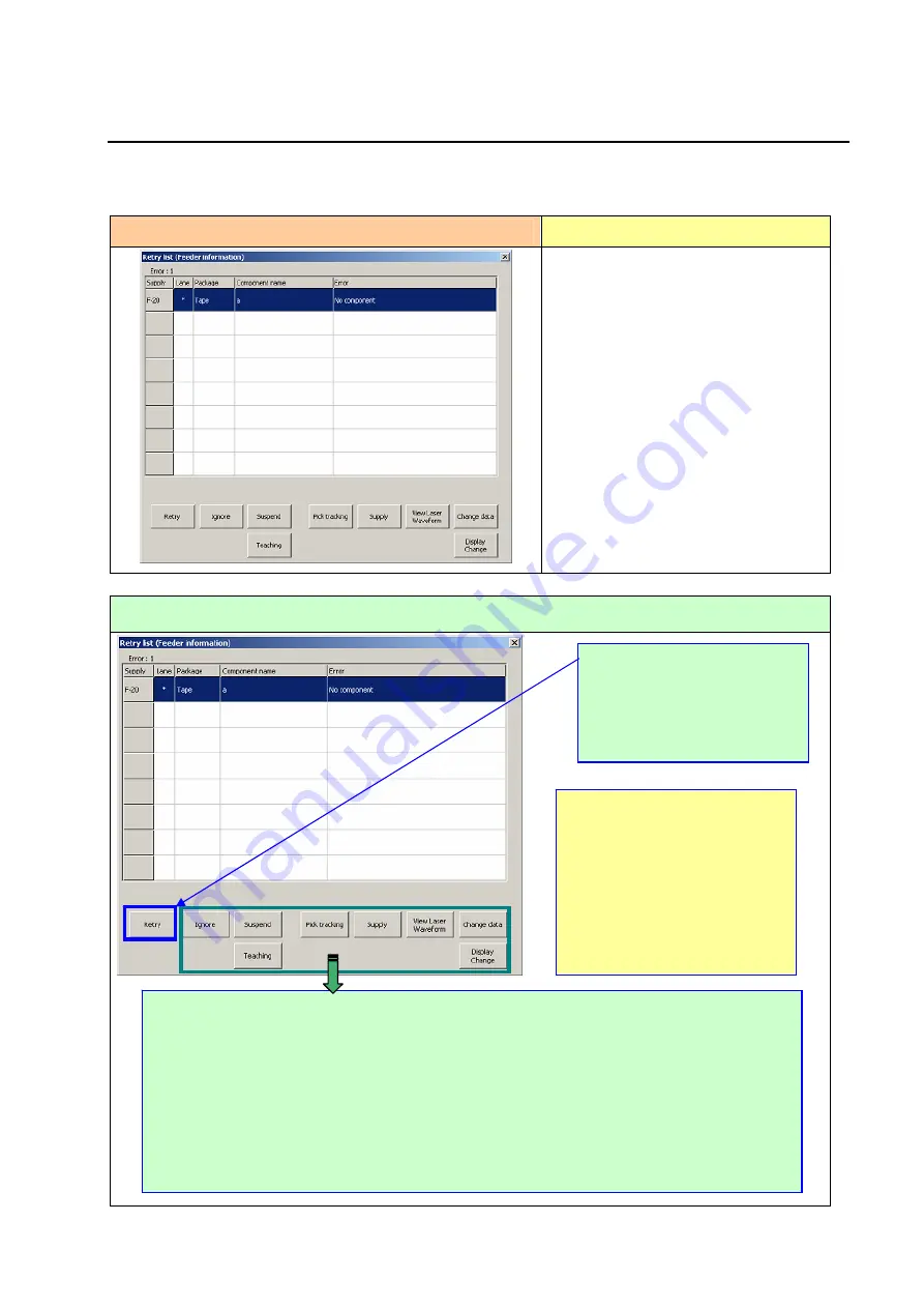
 

Error screen


Causes of the error


① 

The stocked components run out. 

  The machine failed to pick up a 

component. 


(Due to jammed peel-off tape or a 

pick-up position error caused by 

defective tape feeding)


How to handle an error 


 Ignore: 

  Skips a component that caused a component run-out error to produce the next PWB. 


Suspend: 

  Suspends the current PWB production. 

 Pick tracking:

    Uses a camera to execute the component pick-up position correction process. 


Supply: 

  Allows you to set the number of components.   


View Laser Waveform: 

  Displays the laser waveform.    See Section 3.4 “When a laser sensor is 

stained” for details. 


Display change: 

  Switches the screens between the “Not placed” list and the “Feeder 

Information.” 


Change data:

    Allows you to change the Component data. 


Teaching

: Pick position tracking can be performed.

After replenishing the machine 
with components or removing the 
cause of a component run-out 
error (such as jamming of tape), 
select the <Retry> button, and 
then press the <START> switch.

*When you press the <CAMERA> 
button of the HOD while the 
machine stops because 
components run out, you can 
recheck the pick-up position where 
a component run-out error 
occurred again.  If a component 
pick-up error is substantial, 
perform a teaching operation. 

Содержание JX-100

Страница 1: ...For Operators Thank you for purchasing a product of our company CAUTION In order to ensure safe use of JX 100 JX 100 LED be sure to read this Manual before using the machine After reading this Manual...

Страница 2: ...or find any error or omission in writing contact our dealer or JUKI Corporation 4 JUKI Corporation shall disclaim all the responsibility for any trouble resulting from the user s abnormal operation r...

Страница 3: ...to the personnel involved 2 Warning prohibition and directive marks Warning prohibition and directives are marked with the following symbols Warning marks Your hands or clothes may get caught by the m...

Страница 4: ...irm that it operates normally 3 Make sure that the warning label stuck to the machine will be always clearly visible If it has been peeled off or stained order new labels from our company and exchange...

Страница 5: ...rease adheres to your eyes or other parts of your body 3 If grease is mistakenly swallowed immediately consult a physician to prevent diarrhea or vomiting Maintenance 1 To prevent accidents due to una...

Страница 6: ...ted with the main memory Therefore when you save a file onto the drive C the main memory is used and it weighs down the system When you repeat saving data on the drive C the amount of the memory becom...

Страница 7: ...uring production 3 1 3 1 When components run out If the check box Stop system when components run out is checked on the Operation option screen 3 1 3 2 When components run out If the check box Stop sy...

Страница 8: ...uble quotation marks A key is enclosed with angled brackets and Example ESC and ENTER A manual name is enclosed with double quotation marks Example JX 100 Instruction Manual When two or more names tha...

Страница 9: ...onent Head Nozzle Auto Tool Changer ATC This is a unit that stores nozzles Height Measurement System HMS This is a sensor that measures the height of a board or a component mainly Option HMS Support t...

Страница 10: ...Keyboard Mouse These devices operate each screen displayed on the LCD Operations of these devices are similar with those of a personal computer Main switch This switch turns on or off the power of the...

Страница 11: ...tions of the machine change due to cleaning of the nozzle or change of the reference pin position set the Machine setup items again Refer to Section 4 4 Machine setup of the Operation Manual II 6 Refe...

Страница 12: ...to their home positions by pressing OK on the screen above the machine starts operating With the cover open the machine cannot be operated However do not put the hand and face into the machine in any...

Страница 13: ...e Select Refer to Section 2 4 Warming Up of the Instruction Manual CD for details of the Warming up screen Select what to be warmed up Enter the time duration when the machine stops the number of time...

Страница 14: ...lect the desired production program and select the Open button If the PWB width is different from the conveyor rail width adjust the rail width For the adjusting method refer to Step 5 Procedure 1 Sel...

Страница 15: ...The production screen is displayed If you have to make various settings such as setting of the conveyor width according to a PWB to be produced Go to Step 5 If you do not have to make any settings su...

Страница 16: ...s provided under the knobs on both sides of transport View of rear Turn the knobs on both sides and adjust the conveyor rail width to the PWB to be used Refer to Step 3 After completing the adjustment...

Страница 17: ...Setup When pushing the PWB against the stopper check whether it is stable If stability is not found for example because the stopper is in contact with the PWB notch loosen the screw and then adjust th...

Страница 18: ...le on the Transport independent control screen Check the support pin position Push down the PBW lightly from above with a hand to make sure that the PWB is supported by support pins 1 Select Support t...

Страница 19: ...g in side and make sure that the PWB can flow smoothly continuously The Transport control screen is displayed 1 Select PWB transport Shape clamp Select PWB ejection and press EXEC Then the PWB is carr...

Страница 20: ...nel Load a board From the menu bar of the production screen select Production function Quick Setup Display the shape clamp position setting screen From the dialog in which the Teaching button is displ...

Страница 21: ...era teaching screen Do not put a hand into the machine or bring the face and head close to the machine to prevent the human body from being injured CAUTION Adjust the position so that the line on whic...

Страница 22: ...injury do not put your hand face or head inside the machine or move any of them close to the machine Refer to Section 4 5 2 Teaching of the Instruction Manual CD for details of how to teach WARNING 1...

Страница 23: ...axis reference pin into the hole of the fixing plate while sliding the tape feeder horizontally from the front to the rear Check to see if the X axis reference pin is inserted into the corresponding...

Страница 24: ...touch panel From the menu bar of the production screen select Production function Quick Setup Select Supply Device and perform X Y pick coordinates and Z pick height tracking The Pick position tracki...

Страница 25: ...e menu bar of the production screen select Production function Quick Setup Select Supply Device and perform X Y pick coordinates and Z pick height tracking The process is automatically finished After...

Страница 26: ...t component See Section 4 5 4 4 Confirmation of the Instruction Manual CD for details of how to track a component pick up position with a camera If the component pick up position X Y and Z is shifted...

Страница 27: ...Operation manual 2 17 After checking teaching all the components quit Quick Setup Go back to the Production screen Select the OK button Select the OK button...

Страница 28: ...en you press the START switch the machine starts operating To avoid risk of injury never put your hand or head inside the machine Display the Production screen Start production PWB is loaded Enter a v...

Страница 29: ...When you press it again the Suspend screen appears Step 10 Quit the production screen Display the Production screen Exit production Select OK Then production is stopped Select the button After select...

Страница 30: ...is restored into the initial state Select the OK button The shutdown process starts and the main unit software and Windows XP shut down in this order Turn the main switch to the left by 90 degrees Po...

Страница 31: ...used by defective tape feeding How to handle an error When you press the CAMERA button of the HOD while the machine stops because components run out you can recheck the pick up position where a compon...

Страница 32: ...Uses a camera to execute the component pick up position correction process Supply Allows you to set the number of components View Laser Waveform Displays the laser waveform See Section 3 4 When a lase...

Страница 33: ...Restart mode and press the START switch The system processes the mark according to the Prod Restart mode you specified Selection of the Prod Restart mode is effective for only a board that is current...

Страница 34: ...tops temporarily 2 See Section 5 3 4 Laser align sensor of the Operation Manual II to clean the laser sensor window 3 After cleaning the window press the button and check to see if the stains are remo...

Страница 35: ...n to check to see if it is correct Review the height of a component specified on the Component data screen During normal PWB production Clean the nozzles The error message displayed here varies depend...

Страница 36: ...elect the Mode and press the START switch This button automatically returns a nozzle that caused a nozzle attachment error to the ATC When you select the No button the Z axis moves down to the lower p...

Страница 37: ...dual number to the initial value and clear the no component information When some components remain still clear the no component information The target components for component replenish are tape stic...

Страница 38: ...ery process after the PWB production is aborted abnormally press the START switch The following screen appears When you press the OK button the following screen appears When you press the OK button th...

Страница 39: ...switch to start resuming the PWB production This button allows you to check the component placement point at which the machine will resume PWB production with the camera in order to check whether it i...

Страница 40: ...te Revised locations Revision contents Remarks 00 Nov 2008 First edition 01 Jul 2009 For machine Rev A and environment specification Revised 02 Mar 2010 Supported with a JX 100 LED Revised 03 Jan 2011...

Страница 41: ...i Tokyo 206 8551 JAPAN PHONE 81 42 357 2293 FAX 81 42 357 2285 http www juki co jp Copyright 2008 2013 JUKI CORPORATION The specification and appearance may be changed without notice All rights reserv...

Отзывы: