


Page 15 of 15
MP-CB (CE)
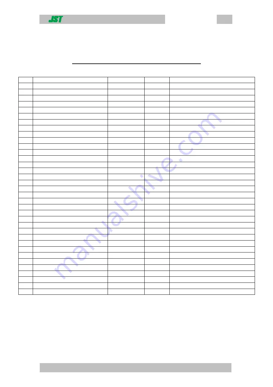
9. Parts list
Parts List For MP-CB (CE) Press Control Unit
Item Description
Part Number
Quantity
Control box location
1.
Gauge 10bar 40mm panel mount
4K8-10P
1
Front panel
2.
Male connector 6mm – 1/8
KQH06-U01
4
Valve / dump valve connections
3.
Bulkhead union 4mm tube
KQE04-00
3
Rear panel connections
4.
Bulkhead female 4mm-Rc1/8
KQE04-01
2
Rear panel / pressure gauge
5.
Branch tee 6mm – 1/8
KQT06-U01
1
Pressure distribution / footswitch outlet
6.
Union tee 6mm tube
KQT06-00
1
Pressure distribution rear panel
7.
Stem reducer 4mm-6mm
KQR04-06
2
Valve and pressure distribution tee
8.
Stem reducer 6mm-8mm
KQR06-08
2
Rear of press, cylinder connections
9.
Stem reducer 4mm-8mm
KQR04-08
1
Output return from on footswitch
10.
Stem plug 8mm
KQP-08
1
Unused output on footswitch
11.
Male run tee 6mm-uni1/8
KQY06-U01
1
Valve main cylincer connection tee
12.
Straight union 4mm tube
KQH04-00
2
Carriage sensor on base of press
13.
Impulse generator 0-30 s
81-507-720
1
Inside case
14.
Single sub base (din rail mount)
81-532-104
1
Inside case
15.
1/8 silencer
AN103-01
3
Main valve and dump valve
16.
Bulkhead union 6mm tube
KQE06-00
2
Press connections – rear panel
17.
Pilot spring valve (5/2)
SYA5120-01
1
Main valve inside case
18.
Plug in ‘or’ gate
81-540-001
1
On rear panel connections inside case
19.
Push button mushroom
VM-30AR
1
Top panel
20.
3/2 plunger actuated valve
VM430-01-00
1
Fitted to part 19 above
21.
Regulator
AR20-F02
1
Top panel
22.
Nut
AR20P-260S
1
Regulator fixing nut
23.
Bulkhead Union 6mm/1/4
KQE06-02
1
Main air inlet
24.
¼ Quick disconnect coupling
AC21CF02
1
Rear panel
25.
¼ Quick disconnect coupling
ACA2593
1
Supply hose to control box
26.
¼ Hose fitting
25802
1
Supply hose to control box
27.
Case
338-1087
1
-------------------------------
28.
Emergency stop legend plate
K2-P550-4
1
Top of case
29.
Male connector 8mm – ¼
KQH08-U02
1
Footswitch supply connector
30
Reducer elbow 4mm – 8mm
KQL04-08
1
Footswitch supply connection
31
Male connector 6mm – ¼
KQH06-U02
2
Pressure regulator connections
32
Male elbow 4mm – M5
KQL04-M5
1
Valve connection
33
Male elbow 4mm – 1/8
KQL04-01S
1
Pressure gauge outlet on regulator
34
Counter
0731 101
1
Front panel
35
Microswitch
321-600
1
Inside case
Содержание MP-CB (CE)
Страница 1: ...MP CB CE Operation manual ...
Страница 12: ...Page 11 of 15 MP CB CE 8 Counter To reset the counter to zero press the blue button ...
Страница 14: ...Page 13 of 15 MP CB CE 10 Pneumatic circuit diagrams MP CB CE used with MP termination press ...
Страница 15: ...Page 14 of 15 MP CB CE 8 Pneumatic circuit diagrams MP CB CE used with a MP cover fitment press or a YA tool ...