9
3.3
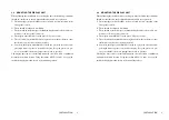
MOUNTING THE DISPLAY UNIT
When planning the installation for your display unit, the following conditions
should be considered to ensure dependable and trouble free operation.
1) The mounting location should be easily accessible to allow operation of the
front panel controls.
2) There should be adequate ventilation.
3) There should be sufficient space behind the display unit to allow cable con-
nections to the rear panel connectors.
4) The display unit should be located near a DC power source.
5) The selected location should be far enough away from device that may cause
interference, such as motors and generators.
6) Generally, the display unit should be located in a protected area away from
prolonged direct exposure to rain and salt spray. It is good practice to pro-
tect your valuable electronic equipment as much as possible.
The display unit can be conveniently mounted on a chart table, or bulkhead
mounted in a desired location. Using the outline of FIG 3-1 and 3-2 as a guide,
install the display unit and secure to the mounting surface.
INSTALLATION
Содержание Radar 3000
Страница 1: ......
Страница 15: ...8 INSTALLATION FIG 3 1 GENERAL SYSTEM DIAGRAM 8 INSTALLATION FIG 3 1 GENERAL SYSTEM DIAGRAM...
Страница 38: ...31 OPERATION MENU ENT Spanish Menus 31 OPERATION MENU ENT Spanish Menus...
Страница 39: ...32 OPERATION MENU ENT Norwegian Menus 32 OPERATION MENU ENT Norwegian Menus...
Страница 55: ......


