
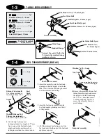
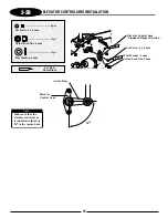
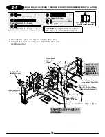

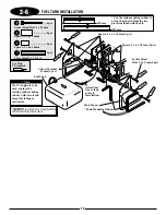
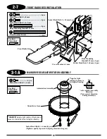
1-2
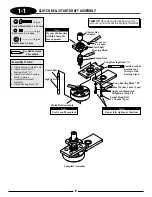
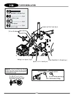
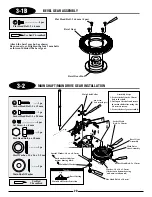
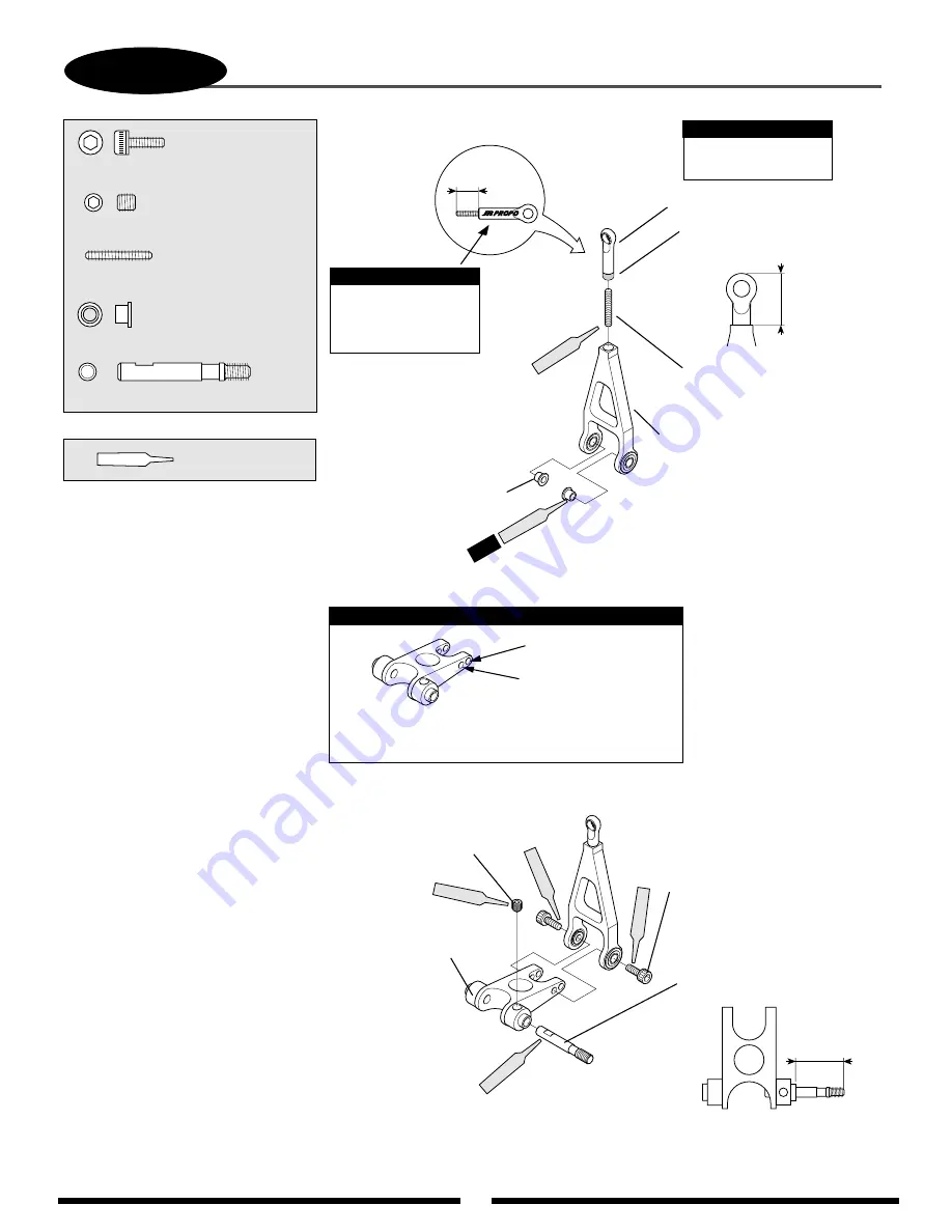
ELEVATOR A-ARM ASSEMBLY
..........................2 pcs
.............................2 pcs
...............................1 pc
............................1 pc
.....1 pc
Socket Head Bolt, 3 x 8 mm
Set Screw, 4 x 4mm
Threaded Rod, 2.3 x 15 mm
A-Arm Bearing Collar
A-Arm Link Base Spindle
Red
Red
Red
Red
18.5 mm
Socket Head Bolt, 3 x 8 mm (2 pcs)
A-Arm
Set Screw, 4 x 4 mm
A-Arm Base
Use Red
Threadlock
A-Arm
Bearing Collar (2 pcs)
11 mm
Red
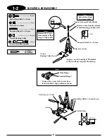
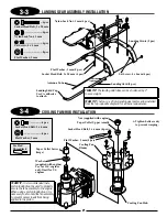
Elevator A-Arm
Remove 1 mm from the bottom
of this link using a hobby knife
Special Universal Link (White)
2 pcs
Red
5 mm
Remove JR
®
Propo
from outside of link
using a hobby knife.
Note:
Oil outside of link
to ease assembly.
Note:
*Connect the A-arm to the A-arm base
in the standard range position as shown.
Wide Range
Standard Range*
Note:
Threaded Rod, 2.3 x 15 mm
Apply a very thin coating of Threadlock
so that it will not seep into the bearing.
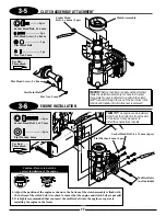
9
Содержание Vigor CS
Страница 64: ...64 E A C D G F DECAL PLACEMENT ...
Страница 65: ...65 B 3 2 5 1 DECAL PLACEMENT ...


