


56
7-6.1
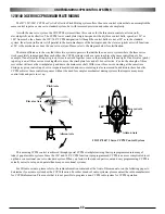
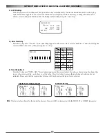
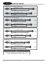
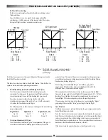
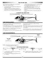
THROTTLE ARM/SERVO HORN POSITIONS
90
1/2 Stick (Throttle) Position
(Throttle Barrel 1/2 open)
Low Stick (Throttle) Position
(Throttle Barrel Fully Closed)
High Stick (Throttle) Position
(Throttle Barrel Fully Open)
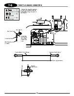
To achieve the correct position of the throttle/servo arm, it may be necessary
to re-position the throttle arm on the carburetor. It may also be necessary to
adjust the length of the throttle linkage slightly to achieve full open and
closed positions of the carburetor.
Throttle Travel Adjustment (Initial Setup Only) 10 Series & Other Systems
It is also possible to increase/reduce the travel of the throttle servo through
the travel adjust function found in most computer radio systems. If this
function is used, make sure the values for the high and low positions remain
equal (same value for high/low). If these values are not equal, it will create
a differential, or uneven movement of the throttle, making rotor rpm
adjustment and fine tuning more difficult.
Throttle Travel Adjustment (Full 3D Setup) with 8103 Systems
When setting up your throttle linkage for cyclic to throttle mixing with
many radio systems, it will be necessary to make any adjustment in the
throttle travel limits by mechanical means only. Move the control linkage in
or out on the servo/throttle arms until the correct barrel travel is achieved.
Please note that it is very important the ATV (travel volume) for both the
high and low throttle setting remain at their maximum values (150%) to
prevent over-travel and binding of the throttle linkage when cyclic to throttle
mixing is used.
For initial cyclic to throttle mixing value information, please refer to the JR
8103 and PCM10X series data sheets located on pages 73-77 of this manual.
Please note that the values and mixing channels shown are universal to most
radio systems currently available.
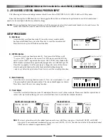
Cyclic to Throttle Channel and Mixing Values (most systems)
*Numbers shown correspond with the correct JR channel numbers
Mixing Value Adjustment
Please note that it will be necessary to determine if the desired mixing
values need to be a + or - value based on servo direction, etc.
To verify the proper direction, move the control surface in each direction
while watching the throttle arm. Throttle should increase each time a control
surface input is given. Adjust the + or - value as necessary until the proper
mix is achieved.
Also check to confirm that the throttle travel is correct and is not causing a
bind in the control linkage after the cyclic mixing has been added.
*To avoid differential throttle travel, make certain both the throttle arm and the servo horn are positioned as shown in the above diagrams.
Mixing Value
Left
Right
20
20
Up
Down
20
20
Mix #1
Channel
Master
Slave
Aileron(2)* Throttle (1)*
Mix #2
Master
Slave
Elevator(3)* Throttle (1)*
Note:
Содержание Vigor CS
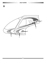
Страница 64: ...64 E A C D G F DECAL PLACEMENT ...
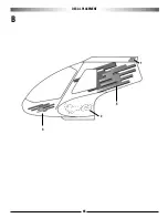
Страница 65: ...65 B 3 2 5 1 DECAL PLACEMENT ...