background image

13

1.  With the system installed in the aircraft, insert the bind plug 

in the bind receptacle. 

2.  Turn on the receiver switch. Note that the LED’s on all 

receivers should be flashing, indicating that the receiver is 

ready to bind.

3.  Establish the desired fail-safe stick positions: normally low 

throttle and aileron, elevator and rudder at neutral. 

4.  Press and hold the bind button on the back of the 

transmitter while turning on the power switch. Within a 

few seconds the system should connect. The LED’s on 

the receivers should go solid, indicating the system has 

connected. 

5.  Remove the bind plug and store it in a convenient place. 
6.  After you’ve programmed your model, it’s important to 

rebind the system so the true low throttle and neutral 

control surface positions are programmed. 

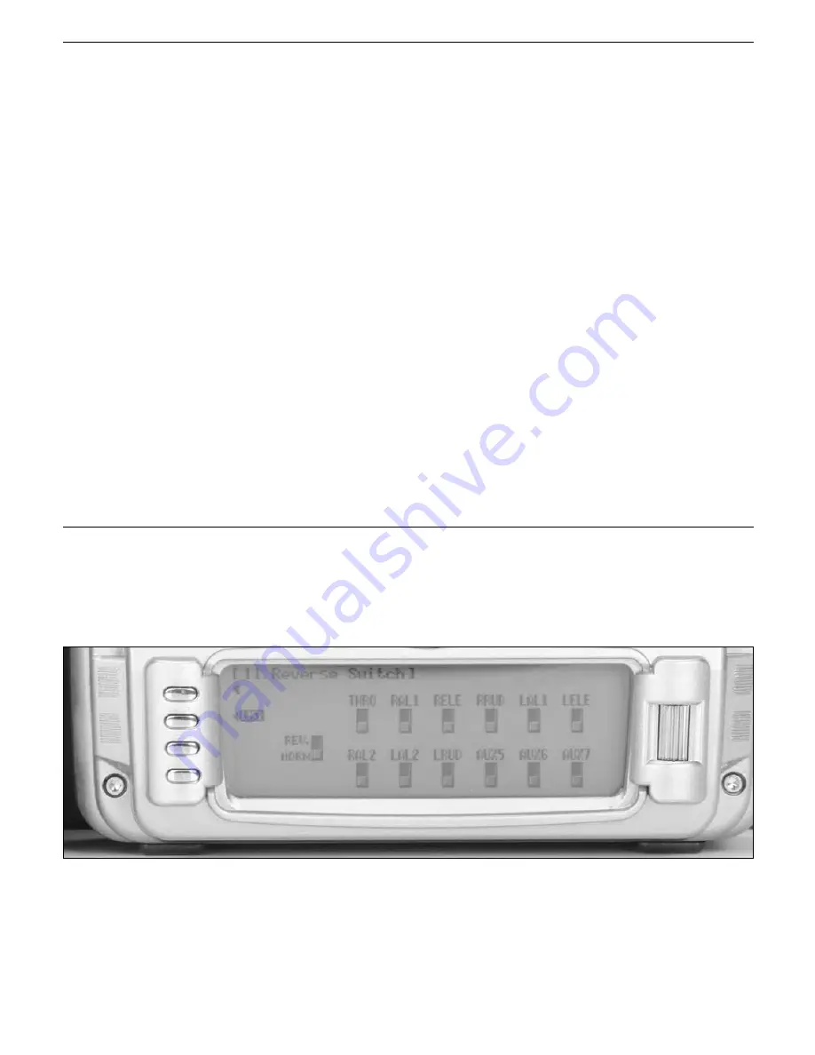
1.  In the Function List screen use the roller to highlight 11. 

REV. SW and press the roller to access the Reverse switch 

screen.

2.  Rotate the roller to highlight the desired channel that you 

wish to reverse and press the roller to reverse that channel. 

Repeat this for all channels. 

Step 9. Binding

Step 10. Servo Reversing

Содержание JR DSM 12x

Страница 1: ...1 APPLICATIONS AND PROGRAMMING GUIDE 12 CHANNEL COMPUTER RADIO SYSTEM WITH SPEKTRUM 2 4GHz DSM TECHNOLOGY...

Страница 2: ...further details regarding programming specifics please refer to the manual Following is a step by step programming guide for Giant Scale aerobatic aircraft The specific example below gives setup deta...

Страница 3: ...roller to access the Model Select screen 3 Rotate the roller to highlight MODEL then press the roller The following screen will appear 4 Rotate the roller to highlight the desired model memory 1 thru...

Страница 4: ...creen use the roller to highlight 28 MDL Reset and press the roller to access the Model Reset screen 2 Press the RESET button then press YES to reset the model memory to Factory Default settings Note...

Страница 5: ...e desired position to place a letter or number up to 16 characters and press the roller to access the Character screen 3 Rotate the roller to select the desired number or letter and press the roller t...

Страница 6: ...rned on Once the aircraft is trimmed using the default settings the trim rate for Aileron Elevator and Rudder can be reduced to 1 to allow for fine adjustments of trim to perfectly trim the aircraft i...

Страница 7: ...e name Throughout the system the short name will be used as the name of the flight mode in functions such as program mixes and other functions 1 In System Mode List screen use the roller to highlight...

Страница 8: ...as desired under each Flight Mode name to select the abbreviated short name A mark indicates the character will be used in the short name a mark indicates the character will not be used in the short n...

Страница 9: ...2 switches combined to select the desired flight mode in flight Generally most fliers use 3 flight modes Flight mode trims can be activated in Device Select With Flight mode trims on trims will be in...

Страница 10: ...Rotate the roller to select the Elevator D R switch then press the roller to select it If another switch is desired choose it in the same manor 5 Rotate the roller to highlight ACT next to Gear then...

Страница 11: ...aileron servo Flaperon for dual aileron servo Delta type for delta wing or elevon models and 4 AILE for 4 aileron servos Also V Tail is selectable as well as Dual Mate functions for Aileron Elevator R...

Страница 12: ...the roller 4 Rotate the roller and highlight 4 Aile and press the roller 6 Rotate the roller and highlight FLAP and press the roller 7 Rotate the roller and highlight INH under RUDD and press the roll...

Страница 13: ...a few seconds the system should connect The LED s on the receivers should go solid indicating the system has connected 5 Remove the bind plug and store it in a convenient place 6 After you ve programm...

Страница 14: ...the mechanical advantage of the surface and an improper mechanical setup can lead to flutter Most giant scale aircraft pilots use different dual rates and expo for each flight mode to customize the ai...

Страница 15: ...highlight the desired EXP value Note the positions POS0 POS1 POS2 are activated via the corresponding D R switch or Flight Mode Switch if selected Press the roller to select rotate the roller to set t...

Страница 16: ...old 3 Rotate the roller to select the HOLD Pos then press the roller Rotate the roller to program the throttle hold position Adjust the throttle hold position so that either the throttle does not move...

Страница 17: ...h between throttle curves on the throttle curve screen once selected move the selected switch to the desired position 3 Rotate the roller to highlight the desired point that you wish to change L 1 or...

Страница 18: ...called negative differential and is useful if an aircraft yaws in the same direction as the Aileron input Most aircraft require a small percentage of positive differential though composite aircraft th...

Страница 19: ...then two columns will appear in the balance screen This also applies to the dual elevator and rudder functions 1 In the Function List screen use the roller to highlight 33 Balance and press the rolle...

Страница 20: ...this will need to be set and adjusted after flying the aircraft 1 In the Function List screen use the roller to highlight 64 RUDD A E and press the roller to access the RUDD A E screen 2 Rotate the ro...

Страница 21: ...the Function List screen use the roller to highlight 54 PROG MIX4 and press the roller to access the PROG MIX4 screen 2 Rotate the roller to highlight INH and press the roller to select 4 Select YES...

Страница 22: ...generally 2 3 is all that is required and press the roller A positive percentage in the mix gives the proper down elevator input without any servo reversing Verify proper direction before flying Adju...

Страница 23: ...the gear switch is used to turn the pump on off 1 In the Function List screen use the roller to highlight 55 PROG MIX5 and press the roller to access the PROG MIX5 screen 2 Rotate the roller to highl...

Страница 24: ...t SW SEL and press the roller 10 Rotate the roller to highlight OFF next to EXP and press the roller to set Expo to ON to smooth the response curve 11 Many smoke pumps turn on when positive values are...

Страница 25: ...ler to highlight THRO then press the roller to access the Throttle stick position option screen 4 Rotate the roller to highlight POS then press the roller to access the Throttle stick position value R...

Страница 26: ...cept that value SPS0 Switch position 5 Rotate the roller to highlight Set Time then press the roller to access the pre programmed time Rotate the roller to select the desired down time typical flight...

Страница 27: ...ght regimes and auto land active to control the landing flaps with throttle Use the following to locate the correct locations for the servos Left Flap Servo Channel 7 Aux2 Right Flap Servo Channel 6 A...

Страница 28: ...8 Using the roller highlight 17 DeviceSEL and press the roller to access the Device Select screen 9 Rotate the roller to highlight ACT next to AUX2 then press the roller The available functions list s...

Страница 29: ...r the System Mode List screen 2 Using the roller highlight 22 Wing Type and press the roller to access the Wing Type screen 3 Rotate the roller and highlight INH under FLAP and press the roller 4 Rota...

Страница 30: ...roller Rotate the roller to increase the auto land setting to 95 It is recommended that the throttle position be set very high at first between 90 99 to give the aircraft a chance to regain some spee...

Страница 31: ...yment Press the roller when set This value will be adjusted after flying the aircraft to prevent the aircraft from nosing up when the flaps are deployed 10 Rotate the roller to highlight the FLAP sett...

Страница 32: ...on throttle up While this setup guide is specific to 120 CCPM helicopters heading lock gyros and Rev Max governors setup of other types and brands of equipment will be similar Use the following to loc...

Страница 33: ...e roller to access the Model Select screen 3 Rotate the roller to highlight MODEL then press the roller The following screen will appear 4 Rotate the roller to highlight the desired model memory 1 thr...

Страница 34: ...SEL and press the roller to access the Type Select screen 2 Rotate the roller to highlight HELI then press the roller to enter the HELI program Note All programming in the selected model memory will b...

Страница 35: ...t and press the roller to access the Model Reset screen 2 Press the RESET button then press YES to reset the model memory to Factory Default settings Note All programming in the selected model memory...

Страница 36: ...e desired position to place a letter or number up to 16 characters and press the roller to access the Character screen 3 Rotate the roller to select the desired number or letter and press the roller t...

Страница 37: ...ed that when using a heading lock gyro that the Rudder trim rate be reduced to 1 to allow fine accurate adjustment of the rudder trim and for Nitro powered helicopters the throttle trim should be redu...

Страница 38: ...he Device Select screen 3 Rotate the roller to highlight INH next to Aux2 then press the roller The available functions will appear 4 Rotate the roller to highlight GOV then press the roller to activa...

Страница 39: ...t screen use the roller highlight 34 Swash TYP and press the roller to access the Swash Type screen 3 Rotate the roller to select the desired swash plate type normally 3 servo 120 see your helicopters...

Страница 40: ...h the throttle channel BEC insert the bind plug into the battery port and proceed to Step 2 1 In Function List screen use the roller to highlight 11 REV SW and press the roller to access the Reverse s...

Страница 41: ...the roller highlight 15 Sub Trim and press the roller to access the Sub Trim screen 2 Rotate the roller to highlight the desired channel that you wish to adjust the sub trim and press the roller to a...

Страница 42: ...en combined high cyclic rates are input 4 Activate the swash plate EXPO by highlighting OFF next to EXP and press the roller to select on Swash plate EXPO is highly recommended as this function compen...

Страница 43: ...D R EXP and press the roller to access the Dual Rate and Expo screen 2 Rotate the roller to highlight the channel in the upper left of the screen and press the roller Select AILE ELEV or RUDD by pres...

Страница 44: ...ler to access the throttle hold screen and activated throttle hold 3 Rotate the roller to select the HOLD Pos then press the roller Rotate the roller to program the throttle hold position A value of 8...

Страница 45: ...e at this location which can then be adjusted as mentioned above 1 In Function Mode List screen use the roller to highlight 68 PIT CURV and press the roller to access the all servos hold screen Press...

Страница 46: ...in value will automatically be selected in each flight mode Note The Governor must be assigned to a channel in device select to access the Governor function See Step 6 above 1 In Function Mode List sc...

Страница 47: ...ller to highlight THRO then press the roller to access the Throttle stick position option screen 4 Rotate the roller to highlight POS then press the roller to access the Throttle stick position value...

Страница 48: ...pt that value SPS0 Switch position 5 Rotate the roller to highlight Set Time then press the roller to access the pre programmed time Rotate the roller to select the desired down time typical flight ti...

Страница 49: ...meet your specific needs and preferences The following setup utilizes three flight modes Launch Cruise and Land which are selected using the 3 position Elevator Dual Rate switch on the upper left fac...

Страница 50: ...left flap sub trim is set at 225 up as a starting point Then when installing the flap servo arms be sure the spoiler stick is in the up position and camber lever is in the middle position Install the...

Страница 51: ...full function 6 channel sailplanes or a 7 channel receiver to be used for 7 channel electric sailplanes It locates commonly mixed channels like right and left ailerons right and left flaps rudder and...

Страница 52: ...he roller to access the Model Select screen Rotate the roller to highlight MODEL then press the roller The following screen will appear 7 Rotate the roller to highlight the desired model memory 1 thru...

Страница 53: ...in the selected model memory will be reset to factory defaults 3 In System Mode List screen use the roller highlight 28 MDL Reset and press the roller to access the Model Reset screen 4 Press the RES...

Страница 54: ...e desired position to place a letter or number up to 16 characters and press the roller to access the Character screen 7 Rotate the roller to select the desired number or letter and press the roller t...

Страница 55: ...trim 7 Press the LIST button to return to the System Mode screen 1 In the SYSTEM M list rotate the Selector until 17 DeviceSEL is highlighted Depress the Selector to access the Device select menu Init...

Страница 56: ...Press the LIST button to return to the System Mode screen Note The flap lever should remain active 1 In the SYSTEM M list rotate the Selector until 22 Wing Type is highlighted Depress the Selector to...

Страница 57: ...ower switch Within a few seconds the system should connect The LED s on the receivers should go solid indicating the system has connected 6 Remove the bind plug and store it in a convenient place 7 Af...

Страница 58: ...significantly offset to provide adequate down flap throw This issue exists because flaps typically have a large travel down 80 to 90 degrees but very little travel up less than 15 degrees To achieve...

Страница 59: ...l position trailing edge level occurs when the spoiler stick is in the full up position 2 Rotate the Selector to highlight SW select and press the Selector to access the available switches Be sure all...

Страница 60: ...with up to 7 programmable points 1 In the brake system menu code71 rotate the Selector to access the BRAKE ELEV function POS0 This function allows a curve mix for elevator compensation with up to 7 p...

Страница 61: ...Flap Mixes Aileron Differential Camber Adjustment Aileron to Rudder Mixes In Step 7 above Establishing Flight Modes flight modes were programmed to operate from the Elevator D R 3 position switch To s...

Страница 62: ...access the Camber System menu 2 Rotate the Selector to highlight LAIL left aileron next to LAUNCH and press the Selector to access the value With the flight mode switch in the Launch mode rotate the...

Страница 63: ...ating the Selector and then pressing the Selector when Pos0 is highlighted This will automatically access dual rate and expo values that are programmed into position 0 whenever the launch mode is sele...

Страница 64: ...of this it s mandatory to first adjust the flap rates before adjusting the flaperon and elevator mixes Also remember that changing the flap rate values also affects the flaperon and elevator flap mix...

Страница 65: ...flaperon positions are achieved 3 Rotate the Selector to highlight FLAP ELEV mix under Launch Adjust the up and down values such that when the flaps are actuated via the flap lever right lever and th...

Страница 66: ...e desired position Press the LIST button to return to the Function Mode screen 1 In FUNC LIST rotate the Selector until 62 AILE to RUDD is highlighted Press the Selector to access the Aileron to Rudde...

Страница 67: ...n press the Selector to store the desired channel Note that five D R and EXPO positions values are available Pos0 1 2 3 and 4 4 Under AUTO on the right of the screen rotate the Selector until CRUI is...

Страница 68: ...tor is centered The adjustment range is 200 to 200 Negative values move the offset in the up elevator direction Set a value of 100 to start as this will locate the offset at 80 up elevator Press the S...

Страница 69: ...red up and down flaperon positions are achieved 3 Rotate the Selector to highlight FLAP ELEV mix under CRUISE Adjust the up and down values such that when the flaps are actuated via the flap lever rig...

Страница 70: ...lector to highlight the Up or Down values next to CRUISE Adjust the up and down values such that when the flap lever is actuated via the flap lever right lever and the elevator D R switch is in the CR...

Страница 71: ...utomatically selected via the flight mode switch and are adjusted in the Camber System Note Elevator preset positions are active in each flight mode using the elevator trim 1 In FUNC LIST rotate the S...

Страница 72: ...at are programmed into position 0 whenever the launch mode is selected 4 Now rotate the Selector to Pos0 and depress the Selector to highlight the D R values Rotating the Selector changes these values...

Страница 73: ...ue then press the Selector to access that value 3 With the flight mode switch in the upper Land mode give a full right aileron command and rotate the Selector to achieve the desired aileron differenti...

Страница 74: ...ron positions are achieved 3 Rotate the Selector to highlight FLAP ELEV mix under LAND Adjust the up and down values such that when the flaps are actuated via the flap lever right lever and the elevat...

Страница 75: ...e up and down values such that when the flap lever is actuated via the flap lever right lever and the elevator D R switch is in the LAND mode adjust the values to obtain the desired flap positions Pre...

Страница 76: ...76 13568 2008 Horizon Hobby Inc 4105 Fieldstone Road Champaign IL 61822 877 504 0233 www horizonhobby com...

Отзывы: