background image

JOINT MAKING OPERATIONS

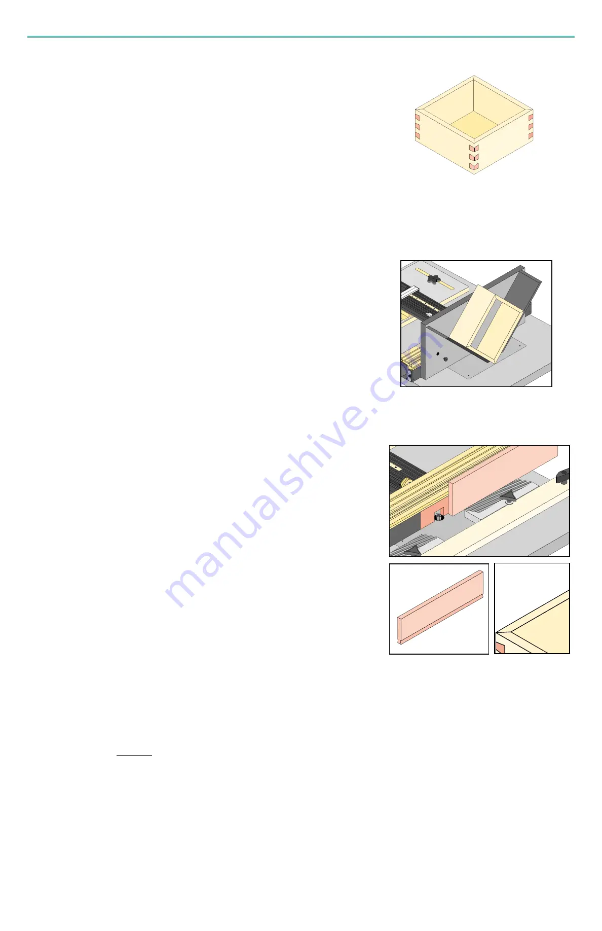
A miter spline is a reinforcement for a mitered corner joint. The weakness in a mitered edge joint is the
relatively small glue area. To overcome this, a spline is often inserted along the length of and centered
in the mitered joint. Decorative miter reinforcing splines are installed perpendicular to the joint and will
be exposed to view.

It is often preferable to have a mitered joint on a project for appearance to hide end grain and make 
finishing easier. If the piece has molded or unusual shapes it may be necessary to use a mitered 
corner.

The spline can be very decorative, requiring only a little imagination. The spline can be a dovetail that
takes on the appearance of a butterfly joint at the corner. Use contrasting colors of wood for the 
maximum decorative effect. Double-dovetail splines can be made by installing a dovetail spline and 
cutting another dovetail within that spline and installing another spline of contrasting wood.

The spline can be cut with a straight bit to resemble a box joint. There can be as many splines as you
want on the corner as long as you maintain the strength of the original miter. The spline can be as
wide or as narrow as you like and can be spaced by using any of the CLINCHER templates or random
spaced.

Construct your project (box) with mitered corners. The corners can be mitered on a table saw using the
miter guage set at 90 degrees and the blade angled 45 degrees, on the router table with a 45 degree
chamfer bit or on the saw table using the Jointech Sliding Crosscut Table and Vertical Miter Fixture.
Plans for constructing these useful shop tools can be found in Jointech’s Woodworker’s Notebook
(Product No. WN-12).

Once the box is constructed you will need a device that will position your box to make the spline socket.
The cut must be made exactly perpendicular to the miter joint. You can use the Jointech Spline Jig
(Product No. SJ-1) or construct your own by following plans also found in the Woodworker’s Notebook.

M ITER S LPI N E JOI NT

(1) Install a router bit for the chosen spline shape. The bit height can be set to the approximate

standard height for that particular bit as found on template plan pages. The height may be 
set deeper if desired, however, do not exceed the maximum cutting height for the bit.

(2) Select a template for spacing or make your own. Center your workpiece for symmetry as 

you would for any other joint cutting operation.

(3) Install the box into the Miter Spline Fixture and clamp in place. Cut all the sockets in one 

corner at a time then reposition the box to the next corner. Don’t force the box through the 
cutter too fast, Make a nice smooth slide past the cutter. Do not pull the work back through 
the cutter for the next cut. Push the workpiece past the cutter and shut off the router. Lift 
workpiece off the fixture, pull back, and reposition the fence to make the next pass.

Making the Sockets

(1) Select a piece of stock long enough to make all the splines and wide enough to grasp and 

run vertically up against router fence. Plane its thickness to be a little wider 
(approximately 

1

/

16”

) than the widest portion of the socket (your dovetail bit diameter).

(2) For dovetail splines use the same cutting bit set at the same height as was used to make 

the sockets.

(3) Set up your fence with horizontal, table mounted featherboards as shown to hold your 

workpiece against fence.

(4) Take very shallow cuts from both sides of the workpiece until you have cut the full dovetail 

profile. Continue taking small cuts from both sides of the board using the thumbwheel to 
move the fence. After each cut make a trial fit to the socket. Using this method an exact fit 
of the spline into the socket can be accomplished.

(5) On a table saw rip the dovetail pin off the edge of your board retaining a small part of the 

uncut portion. Cut the splines into the correct lengths to cover the joint (cut into straight 
lengths - not mitered). Install the splines in the sockets with glue. Clamp if necessary and 
allow glue to dry. Trim the spline ends to match the box and sand.

Making the Splines

Sliding Dovetails are constructed exactly like a blind dovetail except the fit is looser. The fit must
allow the pieces to move smoothly but not so loose as to be sloppy.

Take care when cutting a long dovetail in hard woods. The inverse angle of the groove does not cre-
ate an ideal situation for clearing of chips. With chips in the groove the router bit is repeatedly cut-
ting the same material and generating a lot of heat which is the primary cause for router bit break-
age. For this reason it is necessary to cut the groove in two passes, first with a straight bit to
remove most of the waste, and then with a dovetail bit to complete the groove. For the first pass,
use a 

1

/

4”

straight bit centered to your cut. Install your dovetail bit and make the second pass.

S LI DI NG DOVETAI LS

Jointech Repetitive Scale Templates are useful when you need to cut a series of equally spaced
grooves, multiple thin strips on the table saw, or a series of holes at the drill press, to name a few.
Each Scale Template contains two numbered series of cuts, each with a different spacing. Red
marks are for one series and Black marks for the other to make it easy to tell them apart. There are
18 different series of cutting intervals and range from 

1

/

8”

up to 

7

/

8”

.

R

RE

EP

PE

ET

TI

IT

TI

IV

VE

 S

SC

CA

AL

LE

ES

S

O

U

T

O

U

T

24
Содержание Clincher Fence Machine

Страница 1: ...ING Box joints Double Double Box joints Half Blind Dovetails Double Dovetails Through Double Through Dovetails Jointech s exclusive BoxtailsTM Plus 18 Scales for repetitive cutting Cutting intervals range from 1 8 up to 7 8 Complete Instructions and Setup for Clincher Fence MachineTM and SmartFence Manufactured by Jointech Inc P O Box 790727 San Antonio TX 78279 Customer Svc 210 524 9104 Facsimile...

Страница 2: ...earing protection when operation of power tools Always turn off power to any other tools prior to any adjustment of CLINCHER Allow a cutting tool to come to a complete stop before repositioning of fence sliding section or profile insert If CLINCHER is mounted to a moveable base always secure base to work surface by clamping screws or otherwise fastened before using Always tighten SmartFence slidin...

Страница 3: ...ech Incorporated HOME USE WARRANTY A FULL FIVE YEAR WARRANTY MICRO ADJUST THUMBWHEEL Each detent represents 001 of fence movement Decal indicates which direction fence will move during rotation After an adjustment it s scale sleeve can be re calibrated to Zero Use thumbwheel only when the cam handle clamp is in the micro adjust position CAM HANDLE CLAMP POSITIONS 1 UPRIGHT Carriage is released fro...

Страница 4: ... System These full length videos cover tool selection material preparation resawing table saw setups router setups for jointing and joinery inlays rabbeting sanding gluing up finishing and more After a methodical step by step explanation a final review is made to give you confidence to begin the project Featuring Master Woodworker Jay Hilgeford Jay Hilgeford has been a woodwork instructor and teac...

Страница 5: ...range may be a indication that the machine was not mounted level and true or that there is a slight unevenness or twist in the table s surface This condition can be corrected by one of two ways a At the center of the CLINCHER S range loosen fence fastening hardware and temporarily place a thin shim under each fence end under glide strip or under the side that binds to slightly raise fence Re tight...

Страница 6: ...lways align centerlines of insert and fence to center of router 3 Never turn on router when cutter is within profile of insert without first manually turning cutter to insure clearance 4 To remove insert loosen infeed sliding section and pull apart If necessary use a slot blade screwdriver to pry apart Be careful not to damage or nick sliding section 5 Once fence is centered to cutter if you do no...

Страница 7: ...ence sections close to the cutter leaving 1 8 to 1 4 on each side 3 Loosen both clamping knobs 3 4 turns on outfeed section and push knobs into back of fence see illustration This will disengage indexer rods from keyways on fence body and allow them to be rotated 4 Turn both indexer rods to adjust to the desired offset Each number from 1 to 7 viewed through the windows represents fence offsets in ...

Страница 8: ...nly be sure to orient the pieces with the side marked for the face either up or down for all the pieces Wider grooves can be cut using straight bits preferably spiral upcut bits Mortises of any width can be cut on the table using multiple passes with the saw blade or a dado blade The CLINCHER can be set up as a saw fence to control the width of the cut with absolute accuracy Regardless of the meth...

Страница 9: ...ece and make a cope cut in the scrap piece Check the fit of the scrap cope in a stile If the fit is acceptable make the cope cuts in the rail ends Until the advent of the large horsepower variable speed routers raised panels were made by table saw shaper or by hand with a plane There is now a large selection of router bits horizontal and vertical to choose from A 3 1 2 horsepower router can easily...

Страница 10: ...l cutting bits is completely different than for the horizontal bits The bits are 11 8 in diameter and do not require the large table opening that the horizontal bits do With the smaller diameter bits a lower horsepower router can be used You should have no problem with a 1 1 2 horsepower router but a 1 2 diameter collet is a must To support the panels a tall fence is required The SmartFence and Fe...

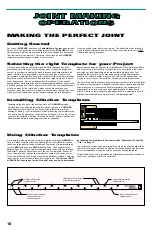
Страница 11: ...d by making successive passes with the cutter This is accomplished using side by side cut lines on these templates Yellow diamonds on some templates are alignment marks which are used to center your workpiece to achieve symmetry MAKING THE PERFECT JOINT Once you have selected your project and the stock thickness has been determined select the type of joint that you want Usually the design and scal...

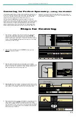
Страница 12: ...ges it s lead screw and micro adjust as necessary to zero the Rabbit to cursor You can now set the Micro adjust thumbwheel scale to zero Lock carriage in place Your workpiece is now centered to the center of your router bit Centering for Perfect Symmetry using the Rabbit It is always desirable to have a dovetail or box joint pattern centered to your workpiece so that the outside pins are of equal ...

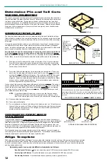
Страница 13: ...mark your boards before you start cutting NOTE If your board edges fall onto or so close to a cut line that you cannot determine which series of cut lines to assign for pins or tails or if the size of the outside pins will be too small you can take the following steps A Choose another template pattern B Trim board widths slightly C Pre cut tail boards on first cut and after cut tail boards on last...

Страница 14: ...e used in the next step to establish which series of cuts RED or BLACK to use for the pins and which to use for the tails 3 Determine Pin and Tail Cuts Find the full size plan page for your selected template pattern to determine the choice for a properly cut tail and pin board Refer to the earlier Section on Making The Perfect Joint Place your board onto plan page and align pencil mark to one of t...

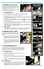
Страница 15: ...for Symmetry Use the CLINCHER Rabbit and the TRU CENTER scale to center the bit on your workpiece following the instructions in the earlier Section on Making The Perfect Joint After finding center lock carriage and install the selected template Take one of your workpieces and place a small pencil mark at its center on one end You can do this by placing it against the fence and up close to the bit ...

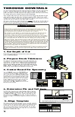
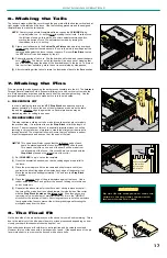
Страница 16: ...joint is assembled Take extra care when making your initial setups 6 Making the Tails The tails are made with all the cuts through the end grain with the boards vertical and at right angles to the table and the fence Use the following procedure and the assigned template lines to make the tail pieces 1 Clamp your tail boards to the Vertical Push Fixture with a backing board as shown Be sure the wor...

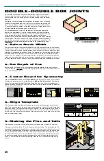
Страница 17: ...ess Mark your workpieces To help keep everything straight gather the four sides of your project and mark each of the inside and outside surfaces number each corner and mark one edge to use as a reference edge to the fence 1 Set Depth of Cut Determine the proper depth of cut following the instructions in the previous section on Half Blind Dovetails 2 Prepare Stock Thickness The method of making thr...

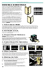
Страница 18: ...ide of the cutter with the Stop Block located on the infeed side Even though you are removing only a small sliver of material in this cut it is in the WRONG direction for the rotation of the bit Exercise great care to hold the workpiece firmly against the fence to prevent the bit from grabbing and throwing the workpiece away from the fence 6 Making the Tails The tails are made with all the cuts th...

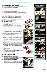
Страница 19: ...t to cursor If an upper symmetry mark is called for from your selected stock width any upper yellow diamond on template can be used 2 Set Depth of Cut Determine the proper depth of cut following the instructions in the previous section on Half Blind Dovetails 3 Prepare Stock Thickness THROUGH Double Dovetails only The method of making through dovetails on a router table requires that your stock th...

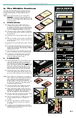
Страница 20: ... the VPF and perform the series of cuts which will mate to the pin workpiece The tail board can now be trial fitted to the completed pin board b SLIDING METHOD 1 Select a suitable workpiece for the middle section The board should be several inches long and same width as your tail and pin work pieces but of thicker stock Plane it to a dimension that is greater than the depth of your dovetail cut by...

Страница 21: ...tock width any lower yellow diamond on template is a symmetry mark for alignment to cursor If an upper symmetry mark is called for any upper yellow diamond on template can be used 2 Set Depth of Cut Set the depth of cut equal to the stock thickness which should also be the same as your router bit diameter DO NOT set the depth slightly greater than your stock thickness as you do for conventional bo...

Страница 22: ...ns The boards should be several inches long and same width as your tail and pin workpieces but of thicker stock Plane each to a dimension that is greater than the depth of your dovetail cut by the wall thickness amount found on the respective full size plan page As in the previous method test cuts will determine the precise thickness required to achieve uniform wall thickness 2 Perform the assigne...

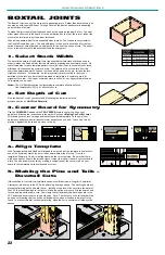
Страница 23: ...2 A for all dovetail cuts 2 Set Depth of Cut Find the depth of cut for your dovetail bit following the instructions in the previous section on Half Blind Dovetails 3 Center Board for Symmetry Use the CLINCHER Rabbit and the TRU CENTER scale to center the bit on your workpiece following the instructions in the earlier Section on Making The Perfect Joint After finding center lock carriage and instal...

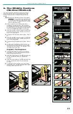
Страница 24: ... glue in place Allow to dry 4 Clamp the tail middle section workpiece to the VPF and perform the assigned series of dovetail cuts which will mate it to the tail workpiece 5 Fit together to the tail board and glue in place Allow to dry 6 On both pin and tail workpieces place a mark on the middle section part of the workpiece which will extend its length by the wall thickness On a table saw cut off ...

Страница 25: ...t force the box through the cutter too fast Make a nice smooth slide past the cutter Do not pull the work back through the cutter for the next cut Push the workpiece past the cutter and shut off the router Lift workpiece off the fixture pull back and reposition the fence to make the next pass Making the Sockets 1 Select a piece of stock long enough to make all the splines and wide enough to grasp ...

Отзывы: