035-17443-000 Rev. A (800)
Unitary Products Group
23
FILTER PERFORMANCE
The airflow capacity data published in Table 7 represents
blower performance WITHOUT filters. To determine the
approximate blower performance of the system, apply the fil-
ter drop value for the filter being used or select an appropri-
ate value from Table 8.
The filter drop values in Table 8 are typical values for the type
of filter listed and should only be used as a gu ideline. Actual
pressure drop ratings for each filter type vary between filter
manufacturer.
Note: Data includes pressure drop of bottom filter rack.
APPLYING FILTER PRESSURE DROP TO DETERMINE
SYSTEM AIRFLOW
To determine the approximate airflow of the unit with a filter in
place, follow the steps below:
1.
Select the filter type.
2.
Determine the External System Static Pressure (ESP)
without the filter.
3.
Select a filter pressure drop from the table and add to the
ESP from Step 3 to determine the total system static.
4.
If total system static measures an ESP value in the air-
flow table (i.e., 0.20, 0.60, etc.) the system airflow corre-
sponds to the intersection of the ESP column and Blower
Speed row.
5.
If the total system static falls between ESP ESP values
in the table (i.e., 0.58, 0.75, etc.) the static pressure may
be rounded to the nearest value in the table determining
the airflow using Step 5 or calculate the airflow by using
the following example.
Example: It is fouond that the total system static is 0.58” w.c.
using 1-turn pulley. To determine the system airflow, com-
plete the following steps:
1.
Obtain the airflow values at 0.50” and 0.60” ESP.
Airflow @ 0.50”: 3550 CFM
[email protected]”: 3406 CFM
2.
Subtract the airflow @0.50” from the airflow @0.60” to
obtain airflow difference.
3406 - 3550 = -144
3.
Subtract the total system static from 0.50” and divide this
difference by the difference in ESP values in the table,
0.60”-0.50”, to obtain a percentage.
(0.58-0.50) / (0.60-0.50) = 0.8
4.
Multiply percentage by airflow difference to obtain airflow
reduction.
(0.8) x -144) = -115
Subtract airflow reduction value to airflow @0.50” to obtain
actual airflow @0.58” ESP.
3550 - 115 = 3435
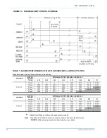
TABLE 8: FILTER PERFORMANCE - PRESSURE DROP INCHES W.C.
FILTER TYPE - BELT DRIVE FURNACE BOTTOM RETURN
Hogs Hair
FIBERGLASS
PLEATED
High Velocity
Disposable
High Velocity
Air Flow Range
(SCFM)
1” THICK
1” THICK
2” THICK
4” THICK
1500-2300
0.05
0.05
0.05
0.05
2300-2800
0.10
0.075
0.10
0.10
2800-3100
0.20
0.10
0.15
0,15
3100-3500
0.25
0.20
0.20
0.20


