035-17443-000 Rev. A (800)
12
Unitary Products Group
An alternate wiring method is to use a field provided 4 x 4 box
and cover on the outside of the furnace. Route the furnace
leads into the box using a protective bushing where the wires
pass through the furnace panel.
NOTE: The power connection leads and wiring box on
upflow units may be relocated to the left side of the furnace.
Remove the screws and cut wire tie holding excess wiring.
Reposition on the left side of the furnace and fasten using
holes provided. Resecure loose wires to prevent contact with
moving parts / hot surfaces and sheet metal edges.
ELECTRICAL CONTROL CONNECTIONS
Install the field-supplied thermostat. The thermostat instruc-
tions for wiring are packed with the thermostat. With the ther-
mostat set in the OFF position and the main electrical source
disconnected, complete the low-voltage wiring from the ther-
mostat to the terminal board on the low-voltage transformer.
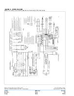
Connect Class 2 control wiring as shown in Figures 8 and 14
“WIRING DIAGRAM”.
Apply strain relief to the thermostat wires passing through the
cabinet.
NOTE: Some electronic thermostats do not have adjustable
heat anticipators. They may have other types cycle rate
adjustment. Follow the thermostat manufacturer's instruc-
tions.
The 24-Volt, 40 VA transformer is sized for the furnace com-
ponents only, and should not be connected to auxiliary
devices such as humidifiers, air cleaners, etc. The
transformer may provide power for an air conditioning unit
contactor.
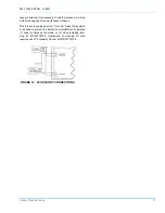
FIGURE 7A
FIGURE 7B
FIGURE 7C
7C
FIGURE 7 : ELECTRICAL WIRING
FIGURE 8 : TYPICAL HEATING AND COOLING
CONTROL CONNECTIONS
Set the heat anticipator in the room thermostat to .45
amps. Setting it lower will cause short cycles. Setting
it higher will cause the room temperature to exceed
the setpoint.
If the furnace is installed with a condensing unit
equipped with its own transformer, the condens-
ing unit control circuit must be isolated from the
furnace transformer. Refer to Figure 9 for con-
nection details.


