


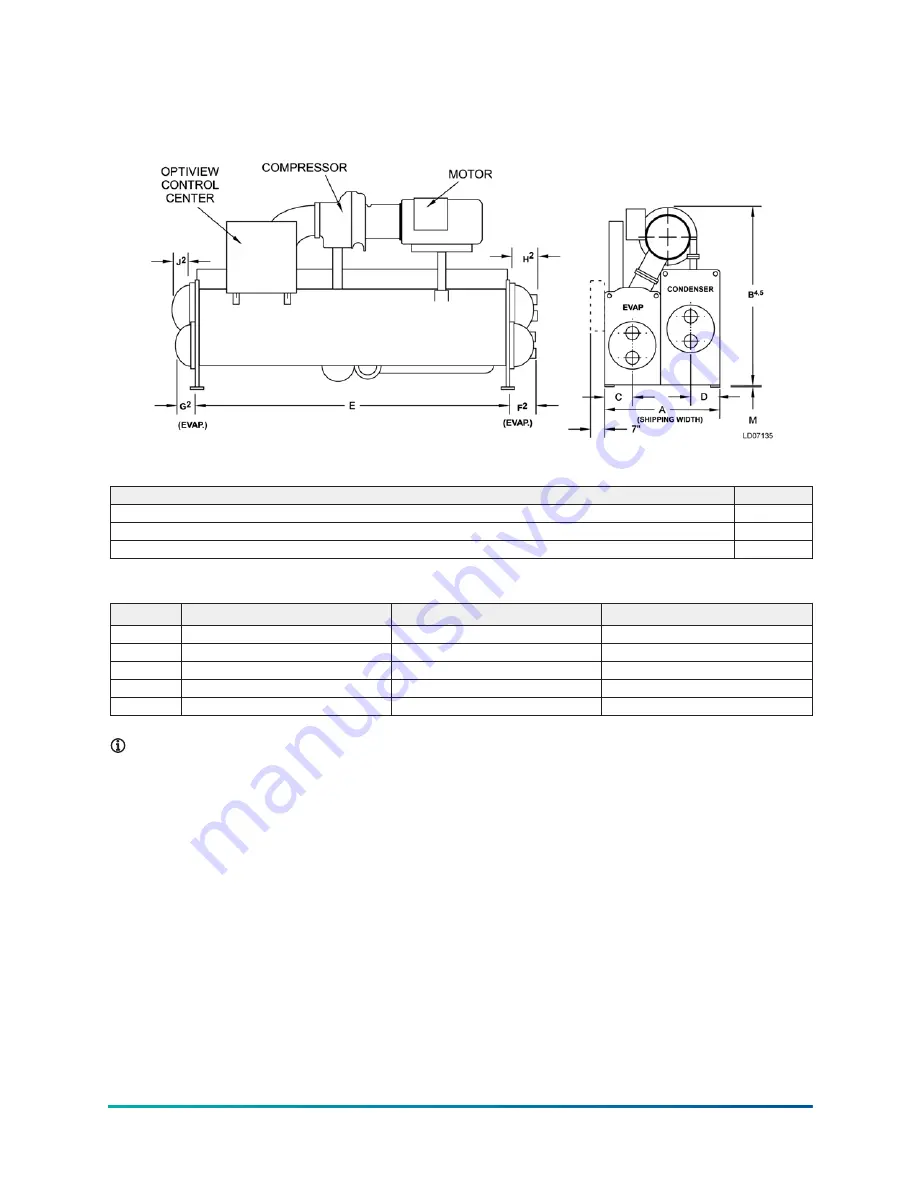
H compressor units (standard)
Figure 15: H compressor unit dimensions (ft in.)
Table 21: Additional operating height clearance to floor
Type of chiller mounting
M (in.)
Neoprene pad isolators
1 3/4
Spring isolators 1 in. deflection
1
Direct mount
3/4
Table 22: H9 compressor evaporator - condenser shell codes
I-K, K–K
K–O
M–M
A
7 ft 6 1/2 in.
8 ft 9 1/4 in.
8 ft 7 in.
B
10 ft 4 in.
10 ft 7 5/8 in.
10 ft 10 1/2 in.
C
2 ft 1 1/4 in.
2 ft 1 1/4 in.
2 ft 4 1/2 in.
D
1 ft 8 in.
2 ft 3 3/8 in.
1 ft 11 in.
E
14 ft 0 in.
14 ft 0 in.
14 ft 0 in.
Note:
1. All dimensions are approximate.
2. For compact waterboxes, see Figure 15, determine overall unit length by adding
waterbox depth to tube sheet length.
3. Water nozzles can be located on either end of unit. Add 1/2 in. (13 mm) to nozzle length
for flanges connections.
4. To determine overall height, add 7/8 in. (22 mm) for isolators.
5. Use of motors with motor hoods may increase overall unit dimensions.
Model YK (Style G) Centrifugal Liquid Chiller
36
Содержание YORK YK Series
Страница 2: ...2 Model YK Style G Centrifugal Liquid Chiller...
Страница 14: ...Figure 3 Long term storage tube side Model YK Style G Centrifugal Liquid Chiller 14...
Страница 19: ...Figure 6 Neoprene isolators in mm 19 Model YK Style G Centrifugal Liquid Chiller...
Страница 20: ...Figure 7 Spring isolators in mm Model YK Style G Centrifugal Liquid Chiller 20...
Страница 21: ...Figure 8 Spring isolators continued in mm 21 Model YK Style G Centrifugal Liquid Chiller...


