


126
JOHNSON CONTROLS
FORM 201.21-NM4 (616)
126
JOHNSON CONTROLS
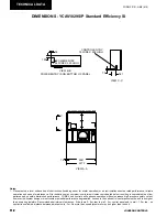
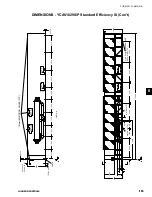
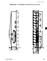
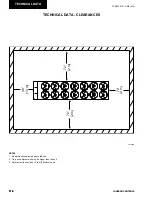
TECHNICAL DATA
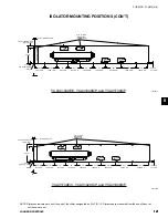
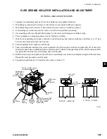
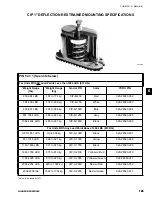
INSTALLATION OF 1" DEFLECTION MOUNTS
1. Floor or steel frame should be level and smooth.
2. For pad installations, isolators do not normally re-
quire bolting. If necessary, anchor isolators to floor
through bolt holes in the base plate.
Isolators must be bolted to the sub-
structure and the equipment must be
bolted to the isolators when outdoor
equipment is exposed to wind forces.
3. Lubricate the threads of adjusting bolt. Loosen the
hold down bolts to allow for isolator adjustment.
4. Block the equipment 10mm (1/4”) higher than the
specified free height of the isolator. To use the iso
-
lator as blocking for the equipment, insert a 10mm
(1/4”) shim between the upper load plate and vertical
uprights. Lower the equipment on the blocking or
shimmed isolators.
5. Complete piping and fill equipment with water,
refrigerant, etc.
6. Turn leveling bolt of first isolator four full revolu
-
tions and proceed to each mount in turn.
7. Continue turning leveling bolts until the equipment
is fully supported by all mountings and the equip-
ment is raised free of the spacer blocks or shims.
Remove the blocks or shims.
8. Turn the leveling bolt of all mountings in either
direction in order to level the installation.
9. Tighten the nuts on hold down bolts to permit a
clearance of 2mm (1/8”) between resilient washer
and underside of channel cap plate.
10. Installation is now complete.
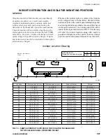
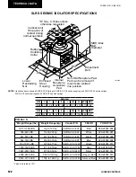
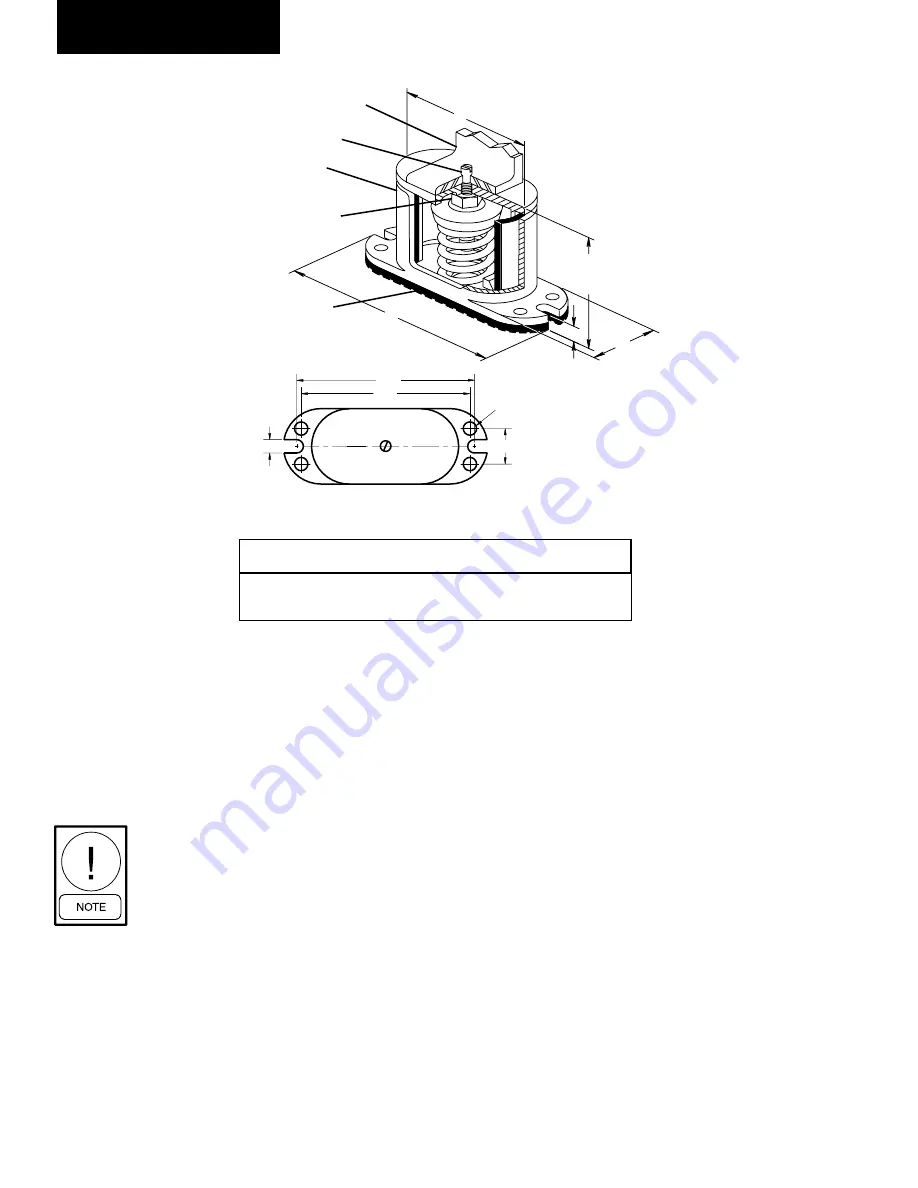
Illustration shows single spring CIP-B or CIP-C mount.
HCL
SBC
Slot Width - SW
HCW
MAX BOLT
DIA. - MBD
BASE PLATE DIMENSIONS
NON-SKID NEOPRENE
ACOUSTICAL ISOLATION PAD
(Bolting to floor is not necessary for
indoor applications)
All springs have additional
travel to solid equal to 50%
of the rated deflection.
A
L
FREE &
OPERATING
HEIGHT
T
W
FERROUS HOUSING
SIDE ACCESS INTERNAL
ADJUSTMENT BOLT
Turn clockwise to load
spring and maintain Free
& Operating Height.
Dowel Pin is 3/8" dia. for
CIP-A & 1/2" thereafter
Mounting may be
operated 1/2" above
Free & Operating
Height.
NOTE-
CIP Mounts are not
to be used in seismic
or wind load
applications.
EQUIPMENT BASE
TYPE CIP DIMENSIONS (inches)†
†Casting dimensions may vary ±1/8"
Size
A
L
T
W SW
HCL HCW MBD SBC
Free
Ht.
CIP-B
8
/4
/2
/16
8
CIP-C
6
/8
/16
/8
5
1
1
7
7
3
3
/8
1
6
/4
3
/
5
/4
3
8
/8
7
/16
9
2
/4
3
3
/2
1
/2
/4
1
1
6
7
/2
/4
1
3
1
1
/4
/8
1
7
7
7
Min
Ht.
5
/4
1
6
/4
3
6
LD10577
Содержание York YCAV1039-1909
Страница 43: ...43 JOHNSON CONTROLS FORM 201 21 NM4 616 43 JOHNSON CONTROLS 6 This page intentionally left blank ...
Страница 55: ...55 JOHNSON CONTROLS FORM 201 21 NM4 616 55 JOHNSON CONTROLS 6 This page intentionally left blank ...
Страница 67: ...67 JOHNSON CONTROLS FORM 201 21 NM4 616 67 JOHNSON CONTROLS 6 This page intentionally left blank ...
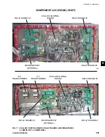
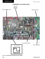
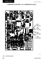
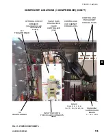
Страница 83: ...83 JOHNSON CONTROLS FORM 201 21 NM4 616 83 JOHNSON CONTROLS 6 035 20890 009 REV LOCATION LABEL CON T LD11141 ...
Страница 229: ...229 JOHNSON CONTROLS FORM 201 21 NM4 616 229 JOHNSON CONTROLS 8 This page intentionally left blank ...
Страница 249: ...249 JOHNSON CONTROLS FORM 201 21 NM4 616 249 JOHNSON CONTROLS 8 This Page intentionally left blank ...
Страница 277: ...277 JOHNSON CONTROLS FORM 201 21 NM4 616 277 JOHNSON CONTROLS 8 This page intentionally left blank ...
Страница 308: ...308 JOHNSON CONTROLS FORM 201 21 NM4 616 308 JOHNSON CONTROLS MAINTENANCE NOTES ...
Страница 309: ...309 JOHNSON CONTROLS FORM 201 21 NM4 616 309 JOHNSON CONTROLS 9 NOTES ...