VA-8122 Proportional Valve Actuator Product/Technical Bulletin
3
M
ounting
IMPORTANT:
Do not use on valves having a
stroke over 5/16 in. Travel beyond
5/16 in. will damage the actuator or
prevent complete shutoff.
Note:
In horizontal piping applications, it is
recommended that the valve be mounted
within 85° of the upright position. When
mounted in vertical piping, the valve must be
protected from moisture.
Unpack the actuator and proceed as follows:
1. Remove the actuator cover by pressing inward on
the plastic tabs while sliding the cover up and
forward.
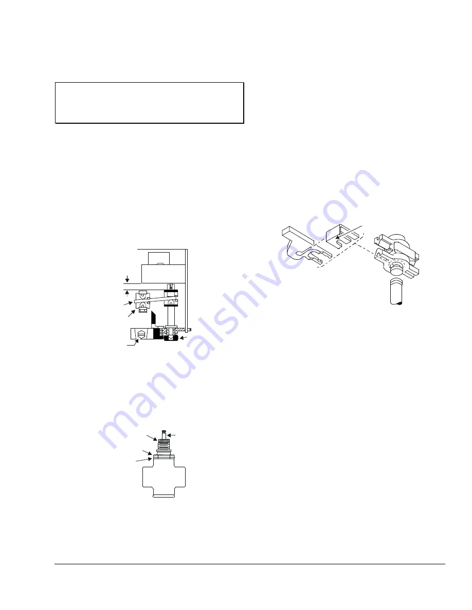
2. Make sure that the lever plate is within 1/4 in.
(6.4 mm) of the upper stop. (See Figure 4.)
Lever Plate
Approximately
1/4 in.
Coupler
Yoke/
Machine Screw
Manual
Adjustment
Knob
Figure 4: Plate Position
3. For VT valves, thread the bonnet adaptor nut
(included in the VA-8020-100 kit) onto the
valve bonnet shown in Figure 5, and tighten with a
wrench until it is snug.
Bonnet
Adaptor Nut
Packing
Nut
Valve
Bonnet
Stem
Figure 5: Valve Bonnet Adaptor
4. Position the actuator yoke on the bonnet adaptor
nut, making sure the yoke is flush with the surface
of the nut.
Note:
If the valve stem is touching the coupler and
preventing a flush contact, use the manual
adjustment knob (shown in Figure 4) to
reposition the coupler.
5. Secure the actuator to the valve bonnet by
tightening the hex-head machine screw provided.
6. Place the stem retainer and coupling clip over the
valve stem, so the lower (shorter) portion of the
coupling clip is positioned in the locking groove on
the valve stem as shown in Figure 6.
Valve Stem
Coupler
Coupling Clip
Stem
Retainer
Lower Portion
of Clip
Figure 6: VA-8020-605 Stem Retainer and Clip Kit
Note:
The extended portion of the stem retainer
must be located on the right so that it lines up
in the window of the cover. It may be
necessary to pull the valve stem up to meet
the coupler or to rotate the manual adjustment
knob (shown in Figure 4) clockwise to run the
coupler down.
7. Push the white plastic stem retainer until the
coupling clip moves forward into the groove, and
the retainer locks the clip in place.
8. Verify that the valve stem is located at the back of
the groove by examining the connection.
To remove the coupling clip, use pliers to grip the stem
retainer and pull outward. (See Figure 6.)


