


Table 4: Camera part numbers and descriptions
Part Number
Description
IPS02-D12-OI04
Illustra Pro Gen4 2MP MiniDome, 2.7-13.5mm,
Indoor/Outdoor, IP67, IK10, TDN w/IR, TWDR
IPS02-D17-OI04
Illustra Pro Gen4 2MP MiniDome, 7-22mm, Indoor/Outdoor,
IP67, IK10, TDN w/IR, TWDR
IPS04-D12-OI04
Illustra Pro Gen4 4MP MiniDome, 2.7-13.5mm,
Indoor/Outdoor, IP67, IK10, TDN w/IR, TWDR
IPS04-D14-OI04
Illustra Pro Gen4 4MP MiniDome, 6-22mm, Indoor/Outdoor,
IP67, IK10, TDN w/IR, TWDR
IPS08-D13-OI04
Illustra Pro Gen4 8MP MiniDome, 3.6-11mm,
Indoor/Outdoor, IP67, IK10, TDN w/IR, TWDR
IPS08-D14-OI04
Illustra Pro Gen4 8MP MiniDome, 6-22mm, Indoor/Outdoor,
IP67, IK10, TDN w/IR, TWDR
Security
Installing the camera onto a surface with a recessed junction box
1.
See steps 1, 2, and 3 in the
Installing the camera onto a wall or ceiling
procedure.
2.
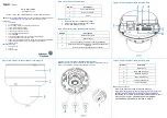
Insert the four screws anchors onto the four holes on the junction box (1)
(Figure 8).
3.
Hold the camera bottom case (2) (Figure 8) up to the junction box and align
the four holes on the camera bottom case with the four holes on the junction
box
4.
Insert the four TP 32mm screws (3) (Figure 8) and securely attach the bottom
case to the junction box.
Figure 8
Installing the camera onto a surface with a recessed junction box
(continued)
5.
See steps 8 to 14 in the
Installing the camera onto a wall or ceiling
procedure to complete the installation.
Installing the camera onto a surface with a junction box
1.
See steps 1, 2, and 3 in the
Installing the camera onto a wall or ceiling
procedure.
2.
Insert the four screws anchors onto the four holes on the junction box (1)
(Figure 9).
3.
Hold the camera bottom case (2) (Figure 9) up to the junction box and align
the four holes on the camera bottom case with the four holes on the junction
box
4.
Insert the four TP 32mm screws (3) (Figure 9) and securely attach the bottom
case to the junction box.
5.
See steps 8 to 14 in the
Installing the camera onto a wall or ceiling
procedure to complete the installation.
Installing the camera onto a surface with a junction box (continued)
Figure 9
Warnings
1. Installation and service should be performed only by qualified and experienced
technicians and comply with all local codes and rules to maintain your warranty.
2. Wipe the camera with a dry soft cloth. For tough stains, slightly apply with diluted
neutral detergent and wipe with a dry soft cloth.
3. Do not apply benzene or thinner to the camera, which may cause the surface of
the unit to be melted or lens to be fogged.
4. To Meet EU EMC immunity requirements for security equipment the mains
power for equipment powering this unit should be backed up by an
uninterruptible power supply.
5. Avoid operating or storing the unit in the following locations:
Near fluorescent lamps or objects with reflections.
Under unstable or flickering light sources.
© 2021 Johnson Controls. All rights reserved. JOHNSON CONTROLS, TYCO and
ILLUSTRA are trademarks and/or registered trademarks. Unauthorized use is strictly
prohibited.


