


VYPER
™
VARIABLE SPEED DRIVE
MAINTENANCE
100.200-IOM (SEP 13)
Page 57
The Following warnings and shutdowns are initiated by the
Vyper drive and communicated to the Quantum
™
LX panel for
display and clearing purposes.
QUANTUM
™
LX LOAD INHIBIT,
FORCE UNLOAD MESSAGES
Load Inhibit - VSD Ambient Temperature
Occurs when the Vyper cabinet temperature reaches 130°F
and this will inhibit the Slide Valve from loading.
Force Unload - VSD Ambient Temperature
Occurs when the Vyper cabinet temperature reaches 135°F
and this will unload the Slide Valve.
Load Inhibit - VSD Converter Heatsink Temp
Occurs when the converter heatsink temperature reaches
155°F and this will inhibit the Slide Valve from loading.
Force Unload - VSD Converter Heatsink Temp
Occurs when the converter heatsink temperature reaches
160°F and this will unload the Slide Valve.
Load Inhibit - Harmonic Filter Baseplate Temperature
Occurs when the harmonic filter baseplate temperature
reaches 175°F and this will inhibit the Slide Valve from
loading.
Occurs when the harmonic filter baseplate temperature
reaches 160°F and this will inhibit the Slide Valve from
loading.
Force Unload - Harmonic Filter Baseplate Temperature
Occurs when the harmonic filter baseplate temperature
reaches 180°F and this will unload the Slide Valve.
Occurs when the harmonic filter baseplate temperature
reaches 165°F and this will unload the Slide Valve.
Load Inhibit - VSD Baseplate Temperature
Occurs when the baseplate temperature reaches 160°F and
this will inhibit the Slide Valve from loading.
Force Unload - VSD Baseplate Temperature
Occurs when the baseplate temperature reaches 165°F and
this will unload the Slide Valve.
Load Inhibit - VSD Phase A Baseplate Temperature
Occurs when the Phase A baseplate temperature reaches
160°F and this will inhibit the Slide Valve from loading.
Force Unload - VSD Phase A Baseplate Temperature
Occurs when the Phase A baseplate temperature reaches
165°F and this will unload the Slide Valve.
Load Inhibit - VSD Phase B Baseplate Temperature
Occurs when the Phase B baseplate temperature reaches
160°F and this will inhibit the Slide Valve from loading.
Force Unload - VSD Phase B Baseplate Temperature
Occurs when the Phase B baseplate temperature reaches
165°F and this will unload the Slide Valve.
Load Inhibit - VSD Phase C Baseplate Temperature
Occurs when the Phase C baseplate temperature reaches
160°F and this will inhibit the Slide Valve from loading.
Force Unload - VSD Phase C Baseplate Temperature
Occurs when the Phase C baseplate temperature reaches
165°F and this will unload the Slide Valve.
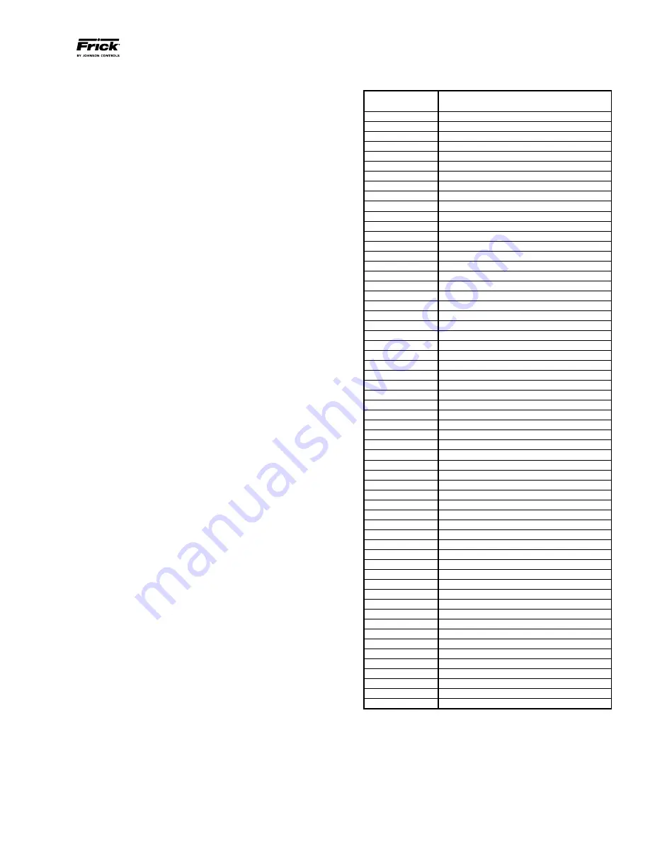
FRICK VYPER
™
FAULT CODES
Quantum
™
LX
Failure Code
Quantum
™
LX Failure Message
1
VSD Interface Board Power Supply Fault
3
VSD Interface Board Motor Current > 15%
4
VSD Interface Board Run Signal Fault
5
VSD Interface Board to Panel Comms Loss
7
VSD Initialization Fault
8
VSD Stop Contacts Fault
9
Harmonic Filter Logic Board Or Comms Fault
10
Harmonic Filter High Total Demand Distortion
11*
High Phase B Inverter Baseplate Temperature
12*
High Phase C Inverter Baseplate Temperature
13*
Low Phase B Inverter Baseplate Temperature
14*
Low Phase C Inverter Baseplate Temperature
17
VSD High Phase A Instantaneous Current
18
VSD High Phase B Instantaneous Current
19
VSD High Phase C Instantaneous Current
21
VSD Phase A Gate Driver Fault
22
VSD Phase B Gate Driver Fault
23
VSD Phase C Gate Driver Fault
24
VSD Single Phase Input Power Fault
27
VSD 105% Motor Current Overload Fault
28
VSD High DC Bus Voltage Fault
29
VSD Logic Board Power Supply Fault
33
VSD Low DC Bus Voltage Fault
34
VSD DC Bus Voltage Imbalance Fault
35
VSD High Internal Ambient Temp Fault
36
VSD High Phase A Inverter Baseplate Temp
VSD High Phase B Inverter Baseplate Temp
VSD High Phase C Inverter Baseplate Temp
37
VSD Logic Board Processor Fault
38
VSD Run Signal Fault
39
VSD High Converter Heatsink Temp Fault
40
VSD Invalid Current Scale Selection
41
VSD Low Phase A Inverter Baseplate Temp
VSD Low Phase B Inverter Baseplate Temp
VSD Low Phase C Inverter Baseplate Temp
42
VSD Serial Communication Fault
43
VSD Precharge Lockout Fault
44
VSD Low Converter Heatsink Temp Fault
45
VSD Current Imbalance Fault
46
VSD Precharge - DC Bus Voltage Imbalance
47
VSD Precharge - Low DC Bus Voltage 2
48
VSD Precharge - Low DC Bus Voltage 1
50
Harmonic Filter High DC Bus Voltage Fault
51
Harmonic Filter High Phase C Current Fault
52
Harmonic Filter High Phase B Current Fault
53
Harmonic Filter High Phase A Current Fault
54
Harmonic Filter Phase Locked Loop Fault
56
Harmonic Filter Logic Board Power Supply
65
Harmonic Filter Precharge - High DC Bus Voltage
66
Harmonic Filter Precharge - Low DC Bus Voltage
67
Harmonic Filter DC Current Transformer 1
68
Harmonic Filter DC Current Transformer 2
69
Harmonic Filter High Baseplate Temp Fault
71
Harmonic Filter Low DC Bus Voltage
75
Harmonic Filter DC Bus Voltage Imbalance
76
Harmonic Filter 110% Input Current Overload
77
Harmonic Filter Run Signal Fault
81
VSD Interface Board NovRAM Failure
83
Harmonic Filter Serial Communication
84
Harmonic Filter Input Frequency Out of Range
* 437 HP drives only