


FRICK
®
POWERPAC
™
INSTALLATION - OPERATION - MAINTENANCE
170.600-IOM (JUN 11)
Page 5
OIL SEPARATOR/RESERVOIR
The oil separator is a horizontal, three-stage design with
integral sump. The separator is designed and constructed
in accordance with ASME Section VIII, Div. 1. Replaceable
coalescent separator elements are provided for final gas/oil
separation of particles down to less than 1 micron.
OIL COOLING
The compressor oil is cooled using a semiwelded plate heat
exchanger that is integral with the refrigerant condenser. The
heat exchanger plates are AISI 316 stainless steel construc-
tion. Maximum design working pressure is 300 or 400 psig.
MOTOR
A factory-mounted flanged motor is close-coupled to the
compressor. The compressor/motor assembly requires no
field coupling alignment. Standard motors are open drip
proof (ODP), have class B insulation, and 1.15 service factor.
SEMIWELDED PLATE CONDENSER
Condenser
Level Sensor
Level Pipe
Motorized
Expansion
Valve
Figure 1 - Semiwelded Plate Condenser
Semiwelded plate heat exchangers have plates constructed
of AISI 316 Stainless Steel. Gaskets are a two-piece construc-
tion for excellent compatibility with refrigerant and cooling
media. The plate heat exchangers can be disassembled for
easy cleaning and capacity modification.
Like the evaporator, the CPHE condenser is a plate heat
exchanger, and the number of cassettes is exactly adapted
to the current operating conditions. Refrigerant condenses
between the welded plates which make up the cassettes,
and the cooling water circulates in the channels between the
cassettes. The plate condenser may have a built-in oil cooler.
The unit can also be equipped with other types of condensers.
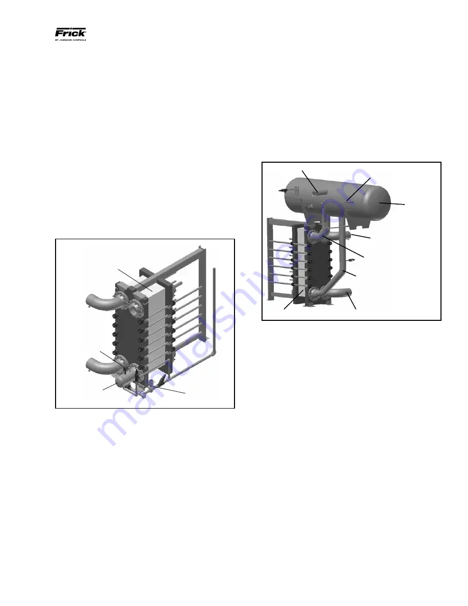
SEMIWELDED PLATE EVAPORATOR
The evaporator is a plate heat exchanger consisting of a
number of cassettes carefully adapted to the actual operating
conditions. The cassettes are assembled/bolted together in
a frame made for the actual design pressure. The refriger-
ant evaporates inside the cassettes and brine is cooled on
the outside.
The evaporator in Figure 2 is of the flooded type, which
means that it is filled with boiling refrigerant. This liquid
leaves the liquid separator and is led to the evaporator
through the drop leg.
Evaporator
Drop Leg
Brine/Water Outlet
Wet Return
Brine/Water Inlet
Liquid Makeup
Liquid
Separator
Dry Suction
Figure 2 - Semiwelded Plate Evaporator
When the water or brine is cooled in the evaporator on its
way through the brine/water connections, the refrigerant
boils and a mixture of liquid and vapor flows through the
wet return and into the liquid separator. From here the su-
perheated vapor is led to the compressor through the dry
suction while the separated liquid is collected at the bottom
of the liquid separator. The system is self-circulating and
needs no pump on the refrigerant side. Liquid runs from the
high pressure side and is supplied to the liquid separator
through the liquid makeup line.
QUANTUM
™
LX CONTROL CENTER
The Quantum
™
LX is a control and monitoring system for
supervision and regulation of the chiller unit. It is factory
mounted and completely wired with all required safety and
operating devices. The control system includes as standard
a single NEMA 4 control panel housing, microprocessor
control, and electrical termination points. Included in the
microprocessor is time-proportioning capacity control, first-
out annunciation, prealarms, volume ratio controls, real-time
clock control, access code protection, lead-lag sequencing,
alternate suction pressure operation, trending, and more.
The operating conditions at the time of the compressor’s
last ten alarms or shutdowns are stored in memory, providing
the ultimate in service and troubleshooting convenience. A
built-in telecommunications interface is standard, enabling
connection to a remote computer or control device.


