


RWH ROTARY SCREW COMPRESSOR UNITS
INSTALLATION
070.620-IOM (DEC 12)
Page 11
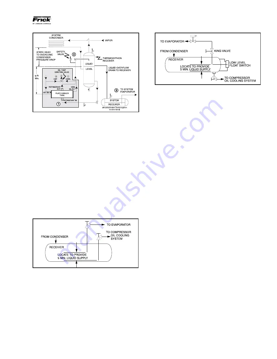
Figure 12 - Level Control
LIQUID LINE SIZES/RECEIVER VOLUME
Liquid line sizes and the additional receiver volume (quanti-
ty of refrigerant required for 5 minutes of liquid injection oil
cooling) can be found in CoolWare.
WATER-COOLED OIL COOLING (OPTION AL)
The watercooled oil cooler is mounted on the unit complete
with all oil piping. The customer must supply adequate water
connections. Determine the size of the watercooled oil
cooler supplied with the unit, as outlined on the Frick P&I
diagram and arrangement drawings.
The water supply must
be sufficient to meet the required flow.
A closedloop system is recommended for the waterside of
the oil cooler. Careful attention to water treatment is es
sential to ensure adequate life of the cooler if cooling tower
water is used.
It is imperative that the condition of cooling
water and closed-loop fluids be analyzed regularly and
as necessary and maintained at a pH of 7.4, but not less
than 6.0 for proper heat exchanger life.
After initial start
up of the compressor package, the strainer at the inlet of
the oil cooler should be cleaned several times in the first 24
hours of operation.
In some applications, the plate and shell oil cooler may be
subjected to severe water conditions, including high tem
perature and/or hard water conditions. This causes acceler
ated scaling rates which will penalize the performance of the
heat exchanger. A chemical cleaning process will extend the
life of the PlateandShell heat exchanger. It is important to
establish regular cleaning schedules.
Cleaning a Plate-and-Shell Oil Cooler:
A 3% solution of
Phosphoric or Oxalic Acid is recommended. Other cleaning
solutions can be obtained from your local distributor, but
they must be suitable for stainless steel. The oil cooler may
be cleaned in place by back flushing with recommended
solution for approximately 30 minutes. After back flushing,
rinse the heat exchanger with fresh water to remove any
remaining cleaning solution.
Figure 10 - TSOC Piping Arrangement
LIQUID INJECTION OIL COOLING (Optional)
The liquid injection system provided on the unit is self
contained but requires the connection of the liquid line sized
as per CoolWare.
It is
IMPERATIVE
that an uninterrupted supply of high pres
sure liquid refrigerant be provided to the injection system
at all times. Two items of
EXTREME IMPOR TANCE
are the
design of the receiver/liquid injection supply and the size of
the liquid line.
It is recommended that the receiver be oversized sufficient ly
to retain a preferential supply of refrig erant for oil cooling.
The evaporator supply must be secondary to this consider
ation. Two methods of accomplishing this are shown. For
large systems, a 5minute retention is used.
The dual dip tube method (Figure 11) uses two dip tubes in
the receiver. The liquid injection tube is below the evapor
ator tube to ensure continued oil cooling when the receiver
level is low.
Figure 11 - Dual Dip Tube
The level-control method (Figure 12) utilizes a level control
on the receiver to close a valve feeding the evaporator when
the liquid falls below that level. Liquid flows preferentially to
the liquid injection oil cooling circuit.
Содержание Frick 1179
Страница 36: ...RWH ROTARY SCREW COMPRESSOR UNITS MAINTENANCE 070 620 IOM DEC 12 Page 36 Figure 37 OIL LEVEL TRANSMITTER ...
Страница 41: ...RWH ROTARY SCREW COMPRESSOR UNITS MAINTENANCE 070 620 IOM DEC 12 Page 41 COMPRESSOR PORT LOCATIONS 408 MM ...
Страница 51: ...RWH ROTARY SCREW COMPRESSOR UNITS MAINTENANCE 070 620 IOM DEC 12 Page 51 OPERATING LOG SHEET ...
Страница 62: ...RWH ROTARY SCREW COMPRESSOR UNITS NOTES 070 620 IOM DEC 12 Page 62 ...
Страница 63: ...RWH ROTARY SCREW COMPRESSOR UNITS NOTES 070 620 IOM DEC 12 Page 63 ...