RXF ROTARY SCREW COMPRESSOR UNITS
INSTALLATION
070.410-IOM (JAN 12)
Page 10
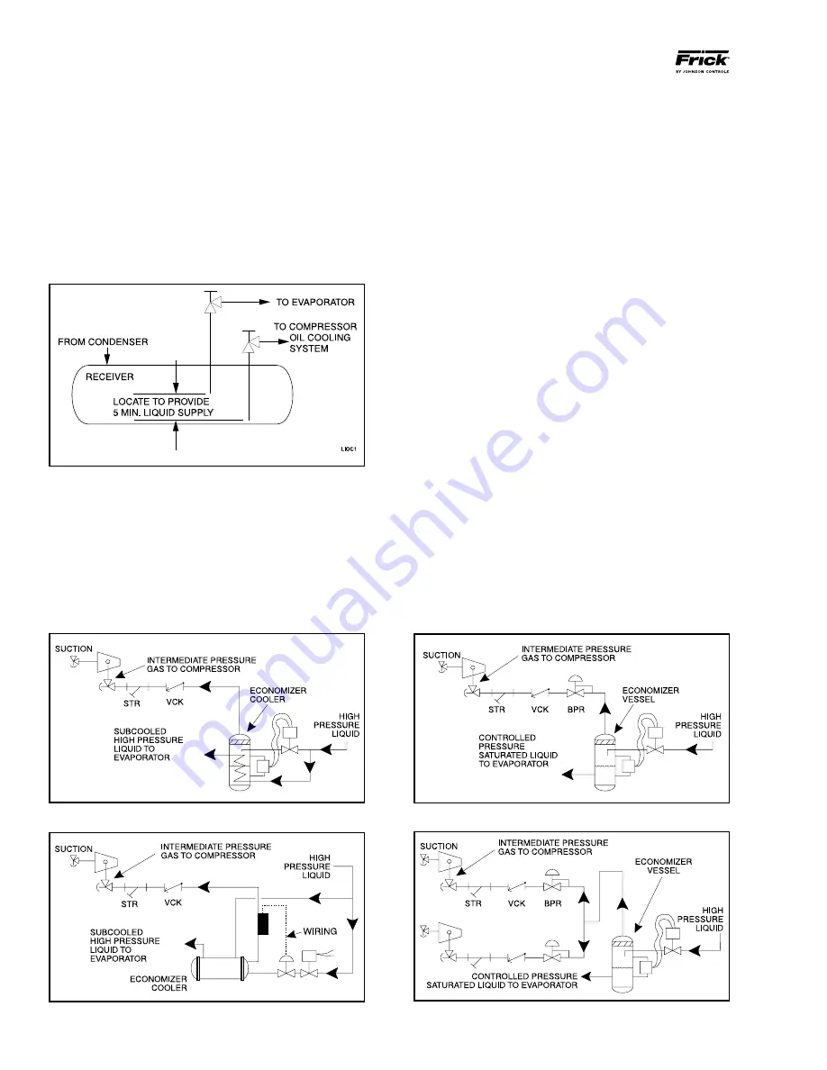
Figure 9 - Direct Expansion Economizer System
Figure 11 - Multiple Compressor Flash Economizer System
intermediate pressure is provided by a port located part way
down the compres sion process on the screw compressor.
As the screw compressor unloads, the economizer port will
drop in pressure level, eventually being fully open to suc-
tion. Because of this, an output from the microproces sor is
generally used to turn off the supply of flashing liquid on a
shell and coil or DX economizer when the capacity falls below
approximately 60%-70% (85%-90% slide valve position). This
is done to improve compressor operating efficiency. Please
note however that shell and coil and DX economizers can be
used at low compressor capaciti es in cases where efficien-
cy is not as important as ensuring that the liquid supply is
subcooled. In such cases, the economi zer liquid solenoid can
be left open whenever the com pressor is running.
Due to the tendency of the port pressure to fall with de-
creasing compressor capacity, a back-pressure regulator
valve (BPR) is generally required on a flash economizer
system (Figure 9) in order to maintain some preset pressure
dif ference between the subcooled liquid in the flash vessel
and the evaporato rs. If the back-pressure regulator valve is
not used on a flash economizer, it is possible that no pressure
difference will exist to drive liquid from the flash vessel to the
evaporators, since the flash vessel will be at suction pressure.
In cases where wide swings in pressure are anticipated in
the flash econo mizer vessel, it may be necessary to add an
outlet pressure regulator to the flash vessel outlet to avoid
overpressurizing the economizer port, which could result
in motor overload. Example: A system feeding liquid to the
flash vessel in batches.
The recommended economizer systems are shown in Figures
8 – 11. Notice that in all systems there must be a strainer
and a check valve between the economizer vessel and the
economizer port on the compressor. The strainer prevents
dirt from passing into the compressor and the check valve
prevents oil from flowing from the compressor unit to the
econo mizer vessel during shutdown.
Figure 8 - Shell And Coil Economizer System
Figure 10 - Flash Economizer System
receiver be oversized sufficiently to retain a 5-minute
supply of refrigerant for oil cooling. The evaporator sup-
ply must be secondary to this considera tion. Failure to
follow these requirements causes wire draw which can
result in damage to the expansion valve, loss of oil cool-
ing, and intermittant oil cooling. One method of ac-
complishing this is described below.
DUAL DIP TUBE METHOD
The dual dip tube method uses two dip tubes in the re ceiv-
er. The liquid injection tube is below the evaporator tube to
assure continued oil cooling when the receiver level is low.
See Figure 7.
Figure 7
ECONOMIZER - HIGH STAGE (OPTIONAL)
The economizer option provides an increase in system capac-
ity and efficiency by subcooling liquid from the condenser
through a heat exchanger or flash tank before it goes to the
evapora tor. The subcooling is provided by flashing liquid in
the economizer cooler to an intermediate pressure level.The


