INSPECTION
Upon receipt of equipment, carefully check all items
against the bill of lading to ensure that all equipment
has been received. Note any discrepancy on the bill of
lading before signing.
Inspect all equipment for any signs of damage caused
during transit. Note any visual damage on the bill of
lading before signing. Immediately report all visual
and concealed damage to the carrier and file a claim.
INTRODUCTION
General
In order to ensure long and trouble free life, the
equipment should have proper care and maintenance.
Enough space should be left around the unit for service
and repair, see .
Equipment, as shipped, is factory assembled as far
as job specifications and shipping limitations allow.
Where field assembly is required, bolts, nuts, screws
and gasketing material are provided with each module.
Modules bolt together from the inside of the upstream
module.
UNIT IDENTIFICATION
To ensure the assembled MQL modules are in the
proper sequence, each module has an identifying code
and an airflow direction label. The proper assembly
sequence is listed on the supply fan nametag. The first
listed module is the first section in the direction of air-
flow.
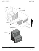
HAND IDENTIFICATION
Coil connections and other components are located
and described as left or right hand. The proper orienta-
tion to describe the proper hand is when airflow is at
your back. Vertical stacked top sections maintain the
same handling as lower section. See
RIGGING AND HANDLING
The MQL air handler can ship as separate modules,
fully assembled, or in separately assembled sections
depending on the unit size and application. The equip-
ment must be rigged as it was shipped from the factory.
Do not remove shipping skid or protective cover until
equipment is ready for final placement, as damage to
equipment can result. Do not remove protective caps
from piping connections until ready to connect piping.
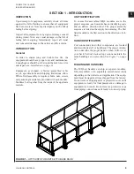
FIGURE 1 -
LIFT POINTS FOR UNITS WITH BASE RAILS
JOHNSON CONTROLS
9
FORM ET102.19-NOM1
ISSUE DATE:08/26/2013
1
SECTION 1 - INTRODUCTION


