


14
ZZ 1019/1E
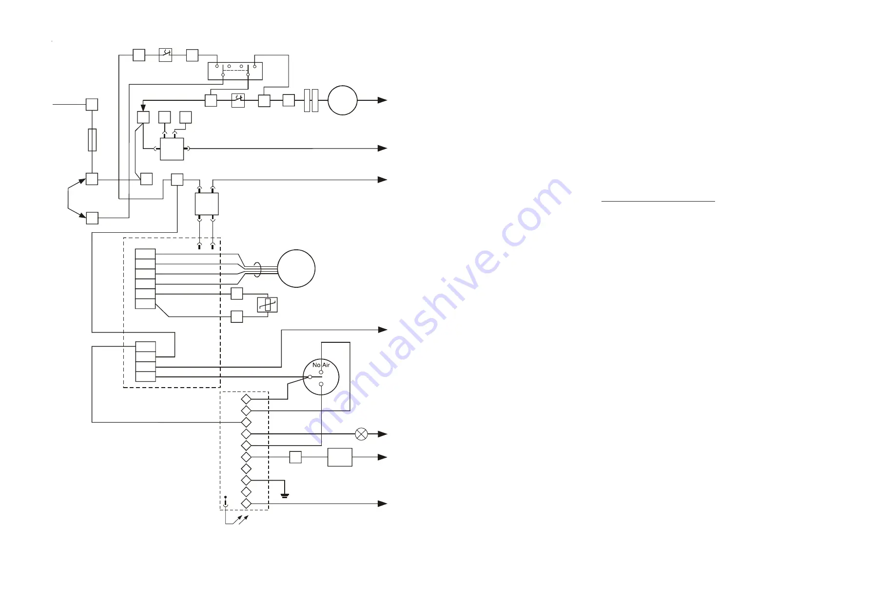
Fig. 8 JANSTAR Mk2 functional flow diagram
ZZ 1019/1E
3
5.1.2
The return air system should be constructed of fire-resistant material. It is extremely important that the correct
size of return air grilles and ducting is used. The return air duct size should be NOT LESS THAN ***mm x
***mm (*in x *in). If flexible duct is used, the duct diameter should be NOT LESS THAN 250mm (10in) dia. The
return air grille should have a free area of not less than 645cm
2
(100in
2
).
5.1.3
An adequate and unobstructed return air path is essential from areas not served by a directly ducted return and to
which warm air is delivered. All such rooms should be fitted with relief grilles which have a free area of
0.0088m
2
/kW (1in
2
/250Btu/h) of heat supplied to the room. The only exceptions are kitchens, bathrooms, and
WC’s.
5.1.4
For top return, a ‘starter’ knockout is provided to assist in creating the required aperture in the fan chamber top.
5.2
WARM DELIVERED AIR
5.2.1
All duct work, including riser ducts, should be fully insulated with 50mm (2in) glass fibre or similar. If extended
duct runs are taken below floor level, these should be similarly insulated and in addition, wrapped with a sound
proof barrier, and protected from crushing.
5.2.2
The duct system should be carefully designed (as detailed in the guidelines in the British Design Manual) to suit
the needs of its specific heating requirements and building layout. The type of duct system, i.e. radial/extended/
stepped plenum should be installed using the least number of fittings to minimise air flow resistance.
6.
INSTALLATION REQUIREMENTS
6.1
AIR HEATER
6.1.1
Heater mounting is by means of five screws (provided) into a wall or structure sufficiently rigid to support the
appliance without deflection (for mounting hole positions see Fig. 8. The weight of the appliance is **kg.
Recommended screw size is No 10 x 2 in with suitable wall plugs. Attach the plenum to the underside of the
appliance using the four M4 x 10 screws and gasket provided.
NOTE:
Ensure that the aperture in the gasket is
correctly aligned with the warm air outlet on the underside of the appliance. Position the return air and warm air
outlet spigots to suit the application before mounting the assembly on the wall. For replacement, the appliance
may be fitted to an existing base plenum, with any blanking plates being mechanically secured and sealed.
6.2
FLUES
(See BS 5440 Pt. 1 Flues)
6.2.1
The maximum allowable flue length is 5.0m plus one 90
o
bend for horizontally flued appliances, and 11.0m plus
terminal for vertically flued appliances.
6.2.2
The minimum allowable flue length is 350mm plus one 90
o
bend for horizontally flued appliances, and the length
of the terminal (1240mm) for vertically flued appliances. For applications where the flue exits directly through a
wall, the telescopic flue supplied with the heater may be used, as shown in Fig. 2.
6.2.3
The horizontal flue shall be installed with horizontal runs having a continuous fall to the terminal of at least 1:50.
(20mm per 1m run).
6.2.4
The overall flue shall be kept as short as possible, with the minimum number of bends. The flue should terminate
in its direction, with the terminal section meeting the outer side of the wall, or roofing at the point where it begins
to flare out, (refer to Fig. 2). One 90
o
horizontal bend is equivalent to 1m of straight flue, a 45
o
horizontal bend is
equivalent to 0.5m of straight flue. One 90
o
vertical bend, where the bend radius is equal to the flue diameter, is
equivalent to 1.3m of flue; one 90
o
vertical bend, where the bend radius is equal to 0.5 flue diameter, is equivalent
to 2.9m of flue; and a 45
o
bend, where the bend radius is equal to the flue diameter, is equivalent to 0.85m of flue.
6.2.5
Sufficient support brackets (not supplied) shall be fitted to bear the weight of the total flue system.
6.2.6
The annular space between the flue assembly and surrounding structure
must
be sealed. If a cement sealant is
used, then the flue pipe must be coated with a suitable varnish a that point, to prevent corrosive attack of the
aluminium pipe.
6.2.7
For a vertical flue, a 60/100mm dia. concentric flue available from Johnson & Starley must to be used.
6.2.8
For a horizontal flue, the terminal supplied must be used. It shall be positioned in accordance with the
recommendations of BS 5440 Pt. 1, Clause 8 and Appendix B, and be guarded against damage and for
protection of passers-by, by using a terminal guard (Tower Flue Components Type K4), obtainable from builders’
merchants and Johnson & Starley (Pt No 1000-0002870).
6.2.9
The flue/air duct spigot on the appliance is female. For horizontal flued appliances, the flue/air duct should be
constructed that such that condensate cannot leak from the joints. Therefore, on vertical runs, all female ends
should face away from the appliance, and on horizontal runs should face towards the appliance, as depicted in
Fig. 3. To reverse the lay of joints, it is recommended to use male/male adaptors, available from Johnson &
Starley (Pt Nos. 1000-0002840 [inner], and 1000-0002850 [outer]). The flue should be constructed working
from the appliance towards the telescopic flue.
TX1
CONTROL MODULE
Fuse
T3.15A
230V 50Hz
Supply
230V
Continuous
Thermostat
(24V)
L
in
k
C8
C9
C10
4
8
10
IG
N
IT
IO
N
C
O
N
T
R
O
L
U
N
IT
br
br
b
br
br
br
b
b
nc
g/y
nc
br
r
y
y
bk
bk
bk
w
w
w
w
g
y
y
b
b
b
br
bk
bk
r
or
or
or
r
r
br
br
br
or
r
br
br
br
br
br
~
~
br
br
br
br
or
0V
14V
b
pk
pk
pk
pk
C3
C7
3
3
7
9
C2
C6
2
2
Air
6
C1
C5
1
1
5
GAS ON
Indicator
Light
Limit Switch
Pressure
Switch
Ignition/flame
Control
Fan Delay
Control
Fan Plug
Summer
Air Flow
Air Heating
ON
CAF
13
11
17
16
15
14
10
7
6
AUTO
TX
3
1
20
18
5
22
ACF
N
N
N
N
N
N
N
MFC
9
C4


