background image

Содержание GSM-500

Страница 1: ...estVirginia 24970 Telephone 304 645 6568 200AEI Drive Lewisburg WestVirginia 24901 Fax 304 645 21E2 MANUAL CONTENTS SPECIFICATIONS DESCRIPTION THEORY OF OPERATION OPERATINGCONTROLS OPERATINGINSTRUCTIONS MAINTENANCE PARTSLIST CHECK SOURCEINSTALLATION Wm B Johnson AssociatesInc Email buyjohnson msn com ...

Страница 2: ...SWITCH SELECTABLE 4 LTNEARRANGES NOTE 0 2 mR H 0 2 mR hr 0 500CPM 0 2 mR H 0 20 mR hr 0 5 000CPM 0 20 mR H 0 200mR hr 0 50 000CPM 0 200mRiH 0 2000mR hr 0 500 000CPM EACH RANGE HAS SEPARATE NON INTERACTING CALIBRATION CONTROLS 4 LINEAR RANGES 0 2 mVhr 0 20 mR hr 0 200mWhr 0 2000 mR hr EACH RANGEHAS SEPARATENON INTERACTINGCALTBRATIONCONTROLS AUTO RANGING 5 OF FULL SCALE IOO O OF FULL SCALE OPTIMIZED...

Страница 3: ...locked full scaleuntil the radiation field at the probe returns to the normal operating range The internal detector can only be dosecalibrated Cst The external detector can be calibrated in doseand cpm The mode of operation doseor cpm is switch selectablefrom the front panel An automatic timed integration feature that provides severaladjustable preset integration times is available for both detect...

Страница 4: ...and 2 input The software selectedfor eachdetector internal and external includesthe DEAD TIME CORRECTION for the CPM operating mode the High Voltage setting for the probe selectedand RESPONSE LINEARIZATION for the probe in the DOSE mode THE INSTRUMENT MUST BE OPERATED IN THE O ZERO POSITION AFTER THE CALIBRATIONS HAVE BEEN COMPLETED When the calibration ofeach probe hasbeencompletedthe operator on...

Страница 5: ...TS IINUTEor DOSEoperationareselected from thefront panelswitchSW2 THE COUNTS MINUTEOPERATINGMODE IS factorycalibratedanddoesnot requirefield calibration TheLED sconnected to pins35 42of Ul aretherangeindicatorsanddiagnostic indicators Figure2 shows thecalibrationcontrols switches located on theCPUprintedcircuitboard 3 3 HIGH LOW VOLTAGE POWERSUPPLIES Six AA sizebatteries provides theLOW VOLTAGE po...

Страница 6: ...TEGRATIONPERIOD INTEGRATESIN DOSEOR CPM MODE AUTO RANGING RANGEINDICATOR IN METER FACE ALL DosE CALIBRATIONS ARE REFERENCEDTo Csl37 4 2 CONTROL DOSE CPM Selects theoperatingmodeof theratemeterto measure eithermR hror countsper minute INTERNAL AND EXTERNAL proberesponse isautomatically linearized in theDOSEmodefor theprobethat hasbeenselected onthe PROBESELECTIONSWITCH SW4insidethehousing Operation...

Страница 7: ...nostic tightsarelit for a fewseconds to showtheyareworking At the ru111 tir the meterisdeflectedto approximatelylz scaleto showit is operating The meterthen revertsto NORMAL operationwith onerangelight lit Thediagnostic circuitsconnected to the BATT PROBElightscontinuously monitortheCircuitry for out of tolerance rangeoperation Batteryvottage below6 8VDC witl light theBATT LED HIGH VOLTAGE that is...

Страница 8: ...o theINTEGRATE INTENAL positior and the CPM DOSE switch adjusted to DOSE for this mode of operation Operating parameters are samefor CPM DOSE operation The GSM 500 will indicate the accumulatedincoming GAMMA DOSE in mR for the time the signal has beenintegrated The sameis true for CPM operation when thc CPM DOSE switch is placedin the CPM position The CPM indication in the INTERNAL mode is in coun...

Страница 9: ... Thetimesavailable are 0o1 5 10 30and60seconds These timesarelistedon theTOP of lhe panetmeterscales in circles FIGURE4 shows an example of a scalewith theINTEGRATE rlMEmarkings qy Theprocedure for usingthisfeatureisasfollows 5 7 1 1Remove theGSM 500bottomhousingby unlatchingtheendlatches andremovingthebottom Housing 5 7 1 2Turn theMAIN SELECTORswitchto INTEGRATEfor theprobeusingtheTIMED COUNT Be ...

Страница 10: ...BJ GSM 5O SPEAKER 1 2gp6 J cev 1 pssg J EXTERNALPROI E OFF OO C NNERNALPROBE o TEGRATTTNTF nNAL O Hfff RNALPRoBo O TNTFcRATEnrIf RNAL o J FRONTPANEL CONTROLS FIGURE 1 copyRtcHT 2006WMB JOHNSON ASSOCTATES ...

Страница 11: ...3 ll ullcD flEaeo H I o r1 1 T 1 1 lJ T lP3 llllll El nfln hn I m r rnr ffi fiil r tr FtlJ H e Uffi E snhi JJpi ilH HnffT q fr Oh ilffiF n ffi1 tr O ffi PH5H2 CPU LOGICBOARD P NT2290 CALIBRATIONcoNTRoLSANDMAJORCOMPONENTS FIGURE 2 GoPYRIGHT 2006WMB JOHNSON ASSOCIATES ...

Страница 12: ...WMBJ GSM sOI POWERSUPPLYBOARDPIN I229I CALIBRATION CONTROLSAND MAJOR COMPONENTS ro t 1 L q m CoPYRTGHT 2006WMB JOHNSON ASSOCTATES FIGURE 3 ...

Страница 13: ...gby unlatchingthelatches on eachendof thebottomhousing 6 2 1 2 ConnecttheDVM to thebatteries Batteries mustreadat least6 5VDC 6 2 1 3 ConnecttheDVM to TP 2 VTVM shouldread5 VDC 0 1VDC 6 2 1 4 ConnecttheDVM to PIN 6 onJ2 Voltageshouldindicate 5 0VDC t 0 f VDC 6 2 1 5 Thiscomplete thetestingof thelow voltagepowersupplies 6 2 2 ADJUST HIGH VOLTAGE POWER SUPPLY FIGURE 3 6 2 2 1 Remove GSM 500from it s...

Страница 14: ... O OF FULL SGALE UTILIZITE FULL SGALE VALUES FOR CALIBRATION IS NOT REGOTIMENDED DUt TO THE PROXITITY OF THE SGALE CHAI GING FACTORS THE RESPONSE ON THE MOST SEIIISITIVE SGALES HAS BEEN SLOWED BY FILTERII G TO ITPROVE ACCURACY T IE GALIBRATION POTEI TIOMETER OI THE X SCALE TUST BE ADJUSTED VERY SLOWLY AI D ALLOW TINE FOR TIIE TETER READII G TO STABILIZ I The GSM 500 can be calibrated in COUNTS MIN...

Страница 15: ...pulsegenerator to 5 000cpmat 0 050V p pamplitude Meter shouldindicatefull scaleon theX10scale 6 2 4 9 Adjustthepulsegenerator to 2500cpmat 0 050Vp pamplitude Meter shouldindicate507oof scaleonthex10range 6 2 4 10 Adjustthepulsegenerator to 500cpmat 0 050V p pamplitude Meter shouldindicatefull scale ontheXlscale 6 2 4 11Adjust thepulsegenerator to 250cpmat 0 050V p pamplitude Meter shouldindicate50...

Страница 16: ...URE 6 2 5 3 Adjust the HIGH VOLTAGE to the voltage indicated for the detector 550 YDC 20 YDC 6 2 5 4 Placethe probe with the PROPER ORIENTATION in a calibrated Cesium 137gamma radiatil field 6 2 5 5 Adjust the radiation field to a known value between 50 75Yo 0 2mVhr of the Xl range 6 2 5 6 Adjust Pl on the right sideof the meter until the GSM 500 indicatesthe correct reading 6 2 5 7 The red led sh...

Страница 17: ...ENTATION in a calibratedCesium137gammaradiationfield 6 2 6 6 Adiusttheradiationfieldto a knownvaluebetween 50 75Yo 0 2mR hr of theXl range 6 2 6 7 AdjustPl ontheright sideof themeteruntil theGSM 500indicates thecorrectreading 6 2 6 8 Thered ledshouldbeXl USE0 2 SCALE FORTHE detectorTO READ mR hr 6 2 6 9 Adjusttheradiationfieldto a knownvaluebetween 20 40o o 0 2nR hr of theXl range 6 2 6 10 Meter s...

Страница 18: ...INAL FOR 6 5vdcOF HIGHER YES Y w CHECK PIN I OF El t t FOR6 5vdcOR HIGHER J v YES t CHECKVOLTAGEAT t PIN 2 OF El FOR 5 vdc 0 1vdc Y I YES I t v CHECKVOLTAGE AT PIN I OF U2 FOR 5vdc r t FORa0 I vdc J v YES CHECK VOLTAGE AT r PIN 5 OF U2 FOR 5 vdc i 0 1vdc I v Y YES J CHECKPINS4 6 OF CONNECTOR J2 ON LOGIC BOARD t w YES I w RETURN FORREPAIR ASSOCTATES NO REPLACE BATTERIES NO r CHECKCOI NECTORJ2A D WI...

Страница 19: ... SEE CHECKBATTERY NO REPLACE BATTERIES FOR 6 5vdc OR HIGHER J v YES v GUIDE 6 2 7 I oscILI oscoPE CHECK FOR OSCILLATIONS r NO CHECK Ql Q2 AT PIN 3 OF T2 l Y YES J v OSCILLOSCOPE CHECK FOR OSCILLATIONS _ NO REPLACE T2 AT PIN 5 OF T2 J YES t J CHECK FORVOLTAGE AT _ NO SEND BACK FOR FOR REPAIR Y v YES I v v CHECKFORHIGH VOLTS NO SENDBACKFORREPAIR JIJNCTION OF RI R Z TIIGH VOLTAGE METER copyRrGHT 2006...

Страница 20: ...t t r BATT LED VOLTMETER VOLTMETf R HV VOLT METER PULSEGENERATOR CHECK BATTERY POSITIVE TERMINAL w I YES I v v CHECK Svdc AT PIN2OFEI PIN 5 OF U2 Y YES J MEASURE IMT r PROBE BNC J I YES J PULSE GENERATOR t PROBEBNC METER DEFLECTS v YES I v t CHECK PROBECABLE NO Y YES Y REPLACE PROBE t NO v J RETURN FOR REPAIR NO NO NO 6 2 3 NONE r REPLACE CABLE copyRtcHT 2006wM B JOHNSON ASSOCTATES ...

Страница 21: ... PULSE GENERATOR CHECKBATTERY POSITIVE TERMINAL J YES v J CHECK FOR SIGNAL AT NO Rf PLACE U5 PIN 10OF U5 v YES Y t CHECKFORSIGNAL NO REPLACE D2 JTJNCTIOND2 D3 SPEAKER l J YES v J CHECK FOR SIGNAL COLLECTORQl J YES CHECKDCVOLTSAT SIDE SPEAKER YES v v REPLACE SPEAKER t J NO v RETURN FOR REPAIR NO REPLACE BATTERIES NO REPLACE Qr NO REPLACE D5 D6 copyRrcHT 2006wM B JoHNSON ASSOCIATES ...

Страница 22: ...PARTS LIST coPYRtGHT 2006wM B JOHNSON ASSOCTATES ...

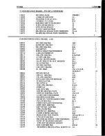
Страница 23: ...8W 1206PKG 22PF50V1206NPOCER 470MF l6V 52PIN PLCC I C SOCKET 0603PKG FERRITE 91K r 8W 1206 PKG 100PFlKV 1808PKG 3OV3OMAMINI3P SCHOTTKYDIODE 249Ku8W 1206PKG 120OHM l 81206PKG 2 5X 2MM RED MINIATURE TESTPOINTS 100210 100242 r00567 100703 10071 I 103742 104022 lo529l t0s402 r05462 r07424 r07479 r08030 108115 108116 108r17 108r18 108119 108123 108128 108217 r08349 108350 108358 108385 108433 r08661 10...

Страница 24: ...206PKG IOO VDC 2OO MW DIODE 3AA PC MOUNT BL BAT HOLDER lK 1 81206 PKG lM 1 8W1206PKG 1 5K1 8W1206PKG 0 1 50v 1206P NPN4OVSOT 23 lMF r6V 1206 PKG 47K 1 8W1206PKG SOT 236OV15OA PNPBIPOLAR 5V REGULATOR MC33172D r C ll0K 1 8w 1206 PKG 470MF16V 2 4K1 8W 1206 lMF sOV6032PKG TANT 1OMF16V3528PKG TANT rA 6OOV RECTIFIERDIODE 200OHM 1 81206PKG 100MF 20V7343PKG ROHSCOMP rM w 2010 PKG CMOSVOLTAGE CONVERTER 100...

Страница 25: ...GSM 5OO WMBJ CHECK SOURCEINSTALLATION copyRrGHT 2006wM B JOHNSON ASSOCTATES ...

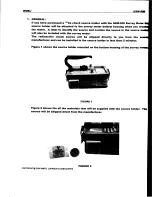
Страница 26: ...ill also be included with the survey meter The radioactive check source will be shipped direcfly to you from the manufacturer and can be installed in the source hotder in less than 5 minutes Figure shows the source holder mounted on the bottom housing of the survey FIGURE Figure 2 shows the all the materials that will be supplied with the source holder Tb source will be shipped direct from the man...

Страница 27: ...he source firmly onto the tape surface D Remove the white paper backing from the Radioactive Material Label E Align the label so it fits onto the middle of the source holder with equat parts of the source holder showing at each edge of the label smooth the label to the source holder with your finger until it is firmly attached Smooth only the edges of the tabet NOT THE MTDDLE OF T tE LABEL F Gompl...

Страница 28: ...APPENDIX MODEL GSP OPERATINGINSTRUGTIONS GoPYRTGHT 2006WMB JOHNSON ASSOCTATES ...

Страница 29: ...GE O 5 mR r gamma radiation 4 OPERATION A CONNEGTTHE GSP TO THE METERBY GONNEGTING ONE END OF A COAXIAL TO THE BNC CONNEGTOR ON THE END OF THE GSP I HOUSING CONNECT THE OTHEREND OF THE COAXIAL CABLETO THE INPUT CONNECTORON TI E METER b FORGENERALSURVEYOPERATIONBE SURETHE SURVEYMETER IAS BEEN ADJUSTED TO 9OOvdc t2O vdc c TURN THE AUDIO SWITGHON d PLACETHE MAIN SELECTORSWITGHIN T IE X POSITION e THE...

Страница 30: ...THE PROBE PLEASEGHECKWITH YOUR RADIATIONSAFETYOFFICER BEFOREATTEMPTINGTHE FOLLOWINGPROGEDURE TO BE SUREYOU ARE COMPLYINGWITH ALL REGUTATORY REQUIREMENTS IF THE METER HAS A HIGH BACKGROUND READING 5oo 25oo cpm WITH NO RADIATION PRESENT THEN THE SURFACE OF THE PROBE IS PROBABLY CONTAMINATED THE PROBE HOUSING CAN BE DECONTAMINATED BY USING A MILD DETERGENT AND Q T PS PAPER TOWELS ETG MOISTEN A Q TIP ...

Страница 31: ...WMBJ GSM 500 SCHEMATICS copyRlcHT 2006WMB JOHNSON ASSOCIATES ...

Страница 32: ... 3 11 l ai l l l l tEl lfrl3l Lr ldlrlHl ll6F t llEiE I lrr r l l lt l Rl irMcinl tlFla I tal lql l lii l El ilsliltl 6tato bl I a t 9l L t6D c B ffi oF o o rrrS rrl coPyRrcHT 2006wM B JOHNSON ASSOCIATES ...

Страница 33: ... tg I rtF I EIR i lF EIF OJ ti 1 ig l 4fi u t i lE l I Htg t coPyRrGHT 2006WMB JOHNSON ASSOCTATES ...

Отзывы: