3
7. Position and installation
1. Remove the ground screws, set up the machine and align it with a spirit level. Then secure the machine with all the screws
and ensure that it is standing stably on the ground. Ensure that the machine also has an adequate earthing circuit to pre-
vent short circuiting. Ensure that the machine is secured against slipping.
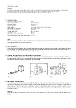
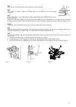
2. Remove the nut on the machine housing B as illustrated in Fig. 3. Lift the column C. Attach it to the machine housing B
by securing the bolt on the machine housing B with the nut A. Should the column become loose after a certain period of
operation, it should be tightened again immediately, as the tyre could otherwise be damaged.
8. Electric and pneumatic connections
Caution:
Prior to installation and connection, ensure that the intended power supply also matches the technical data of the machine.
Electrical and pneumatic equipment may only be installed by an authorised electrician.
Connect the compressed air connection on the right-hand side of the machine to the compressed air system. The power net-
work to which the machine is to be connected must have appropriate fuses and reliable grounding on the outer housing. Install
the automatic pressure release switch on the main power supply. The bleed current is set at 30 mA.
Caution:
The scope of delivery for this machine does not include a mains plug, meaning the user must connect a mains plug with at least
16A which should also correspond to the machine voltage. Alternatively, you can connect the machine directly to the power
supply in accordance with the above specifications.
9. Operating settings
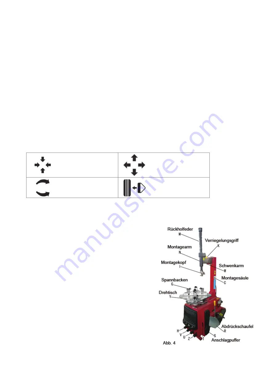
Jaw closing pedal (H)
Jaw opening pedal (V)
Turntable rotating pedal (Z)
Levering pedal (U)
1. Press the turntable rotating pedal (Z). The turntable (Y) rotates in a clockwise direction. Lift the turntable rotating pedal
(Z). The turntable (Y) rotates in a anticlockwise direction.
2. Press the levering pedal (U). The bead breaker blade (R) closes inwards. Release the pedal (U). The bead breaker blade
(R) returns to its original position
.
3. Press the jaw opening pedal (V). The four clamping jaws (G) on
the turntable open. Release the pedal stops the movement of the
jaws. Press the pedal again and the jaws open up to the edge of
the turntable.
4. Press the jaw closing pedal (H). The four clamping jaws (G) on
the turntable close. Press the pedal again and the four jaws stop.
Stepping on the pedal again causes the jaws to close again centred
relative to the turntable.
Note:
The clamping jaws can be opened and closed in any position on the
turntable using the jaw opening pedal, allowing the wheel to be clamped
easily and quickly in position or speedily released. This makes working
more efficient.
The work consists of three parts:
1. Levering the tyre bead
2. Removing the tyre
3. Mounting the tyre
Caution:
Before each use of the machine, ensure that you are not wearing any
loose clothing and wear headgear, gloves and non-slip shoes for pro-
tection. Ensure that you let the air out of the tyre completely and also
remove all wheel balancing weights from the rim.
Содержание Fix Moto
Страница 13: ...11 452 457 453 422 423 442 445 425 616 459 ...
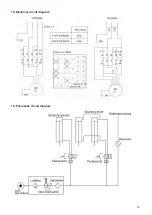
Страница 17: ...15 15 Electrical circuit diagram 16 Pneumatic circuit diagram ...
Страница 18: ...16 ...


