SECTION 7 - BASIC ELECTRICAL INFORMATION & SCHEMATICS
3121200
7-13
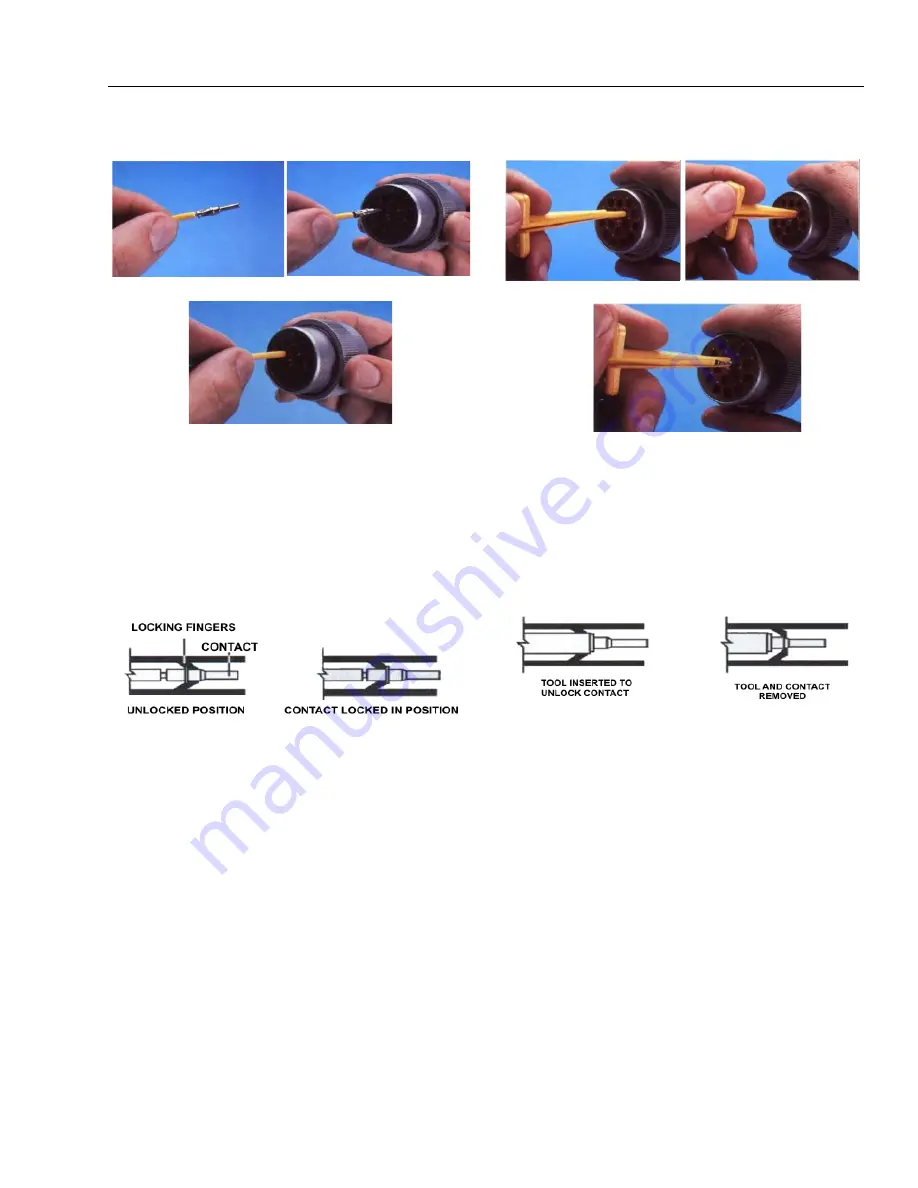
HD30/HDP20 Series Assembly
8.
Grasp contact about 25mm behind the contact crimp
barrel.
9.
Hold connector with rear grommet facing you.
10.
Push contact straight into connector grommet until a
positive stop is felt. A slight tug will confirm that it is
properly locked in place.
NOTE:
For unused wire cavities, insert sealing plugs for full envi-
ronmental sealing
HD30/HDP20 Series Disassembly
11.
With rear insert toward you, snap appropriate size
extractor tool over the wire of contact to be removed.
12.
Slide tool along into the insert cavity until it engages
contact and resistance is felt.
13.
Pull contact-wire assembly out of connector.
NOTE:
Do Not twist or insert tool at an angle.
Figure 7-20. HD/HDP Contact Installation
A
B
C
Figure 7-21. HD/HDP Locking Contacts Into Position
Figure 7-22. HD/HDP Contact Removal
A
B
C
Figure 7-23. HD/HDP Unlocking Contacts
Содержание T500J
Страница 1: ...Service and Maintenance Manual Model T500J PN 3121200 July 25 2018 Rev I AS NZS...
Страница 2: ......
Страница 16: ...xii 3121200 LIST OF TABLES TABLE NO TITLE PAGE NO This page left blank intentionally...
Страница 36: ...SECTION 2 GENERAL 2 8 3121200 NOTES...
Страница 115: ...SECTION 3 CHASSIS TURNTABLE 3121200 3 79 MAE29600 DRIVE MOTOR SPINDLE 1 Figure 3 37 Wheel Drive Removal and Installation...
Страница 136: ...SECTION 3 CHASSIS TURNTABLE 3 100 3121200 Figure 3 41 Battery Cable Routing Prior to SN 0030001804...
Страница 143: ...SECTION 3 CHASSIS TURNTABLE 3121200 3 107 Figure 3 45 Battery Charger Schematic...
Страница 213: ...SECTION 5 BASIC HYDRAULIC INFORMATION SCHEMATICS 3121200 5 39 This page left blank intentionally...
Страница 234: ...SECTION 5 BASIC HYDRAULIC INFORMATION SCHEMATICS 5 60 3121200 NOTES...
Страница 246: ...SECTION 6 JLG CONTROL SYSTEM 6 12 3121200 Figure 6 5 System Test Flow Chart Platform Tests...
Страница 248: ...SECTION 6 JLG CONTROL SYSTEM 6 14 3121200 Figure 6 6 System Test Flow Chart Ground Station Tests...
Страница 283: ...SECTION 7 BASIC ELECTRICAL INFORMATION SCHEMATICS 3121200 7 11 Figure 7 17 Connector Installation...
Страница 297: ...SECTION 7 BASIC ELECTRICAL INFORMATION SCHEMATICS 3121200 7 25 This page left blank intentionally...
Страница 304: ...SECTION 7 BASIC ELECTRICAL INFORMATION SCHEMATICS 7 32 3121200 NOTES...
Страница 305: ......


