SECTION 5 - OPTIONAL EQUIPMENT
3120883
– JLG Lift –
5-1
SECTION 5. OPTIONAL EQUIPMENT
5.1
MOTION ALARM
A motion alarm horn provides an audible warning when
the platform controls are selected at the PLATFORM/
GROUND SELECT switch, the EMERGENCY STOP switch
is ON, and the footswitch is depressed. The alarm warns
personnel in the jobsite area to avoid the operating
machine.
5.2
FOAM FILLED TIRES
NOTE: Foam Filled tires are required on J model machines.
Eliminates flats by filling tires with polyurethane foam. For
use where sharp objects are frequently encountered on
operating surface of jobsite.
5.3
ROTATING BEACON
An amber rotating beacon may be installed on the
machine hood, and is activated whenever platform con-
trols are selected at the PLATFORM/GROUND SELECT
switch. When activated, the light provides a visual warning
of the machine’s operation.
5.4
TILT ALARM
An audible warning horn that will sound when the
machine is out of level three degrees in any direction with
the boom raised above horizontal.
5.5
WHEEL COVERS
Provide protection for wheels and wheel bearings from
dirt, grease, mud, rocks, etc.
5.6
BATTERY PACKS
Spare battery packs are available to enable the operator
to remove battery packs for charging and replace them
with fresh battery packs to keep machine operating with
minimal down time. Battery packs are interchangeable
and include applicable cables and connectors for “plug-
in” use.
5.7
PLATFORM LIGHTS
Platform lights may be installed on the machine platform
rails, to provide more lighting for the operator.
5.8
CONTROL CONSOLE COVER
The control console cover is a one piece clear acrylic
cover which attaches to the platform rails over the control
console. The cover, when in position, will protect the entire
platform control console and the control handle on the
right side of the console.
5.9
CYLINDER BELLOWS
A one piece accordion shaped rubber bellows may be
attached to the rod end of the cylinder barrel and the cyl-
inder rod as close to the rod attach bushing as possible.
The bellows affords protection to the cylinder rod in either
the extended or retracted position. The bellows are
installed on the lift cylinders, slave cylinder, master cylin-
der, and steer cylinder.
5.10 WORK PLATFORM
These machines are available with a 0.76 x1.52M size plat-
form.
Updated 11-3-99
Содержание E45A
Страница 2: ......
Страница 4: ...FOREWORD b JLG Lift 3120883 This page left blank intentionally...
Страница 22: ...SECTION 2 PREPARATION AND INSPECTION 2 6 JLG Lift 3120883 Figure 2 2 Daily Walk Around Inspection Sheet 1 of 3...
Страница 26: ...SECTION 2 PREPARATION AND INSPECTION 2 10 JLG Lift 3120883 Figure 2 3 Lubrication Chart Updated 6 1 99...
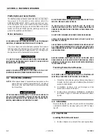
Страница 48: ...SECTION 4 MACHINE OPERATION 4 6 JLG Lift 3120883 Figure 4 2 Upright Positioning Updated 8 4 99...
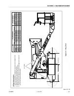
Страница 49: ...SECTION 4 MACHINE OPERATION 3120883 JLG Lift 4 7 Figure 4 3 Lifting Chart Updated 9 21 99...
Страница 50: ...SECTION 4 MACHINE OPERATION 4 8 JLG Lift 3120883 Figure 4 4 Chassis Platform Tie Down Updated 3 15 00...
Страница 52: ...SECTION 5 OPTIONAL EQUIPMENT 5 2 JLG Lift 3120883 This page left blank intentionally...
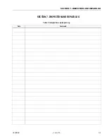
Страница 56: ...SECTION 7 INSPECTION AND REPAIR LOG 7 2 JLG Lift 3120883 Table 7 1 Inspection and Repair Log Date Comments...
Страница 58: ......
Страница 59: ......

