USR-WIFI232-A/B/C User Manual
http://www.usriot.com
Jinan USR IOT Technology Limited
Page 9 of 93
Figure 3
WIFI
WIFI
WIFI
WIFI connection
connection
connection
connection
Now, nlink led of USR-WIFI232-A Evaluation Board is lighting.
1.3
1.3
1.3
1.3 communication
communication
communication
communication test
test
test
test
Module
’
s default setting:
�
SSID:
SSID:
SSID:
SSID:
USR-WIFI232-A;
�
Encryption
Encryption
Encryption
Encryption mode
mode
mode
mode::::
open
,
none;
�
UART:
UART:
UART:
UART:
57600,8,1,None;
�
Network
Network
Network
Network parameters
parameters
parameters
parameters
:
TCP,Server,8899,10.10.100.254;
�
IP:
IP:
IP:
IP:
10.10.100.254;
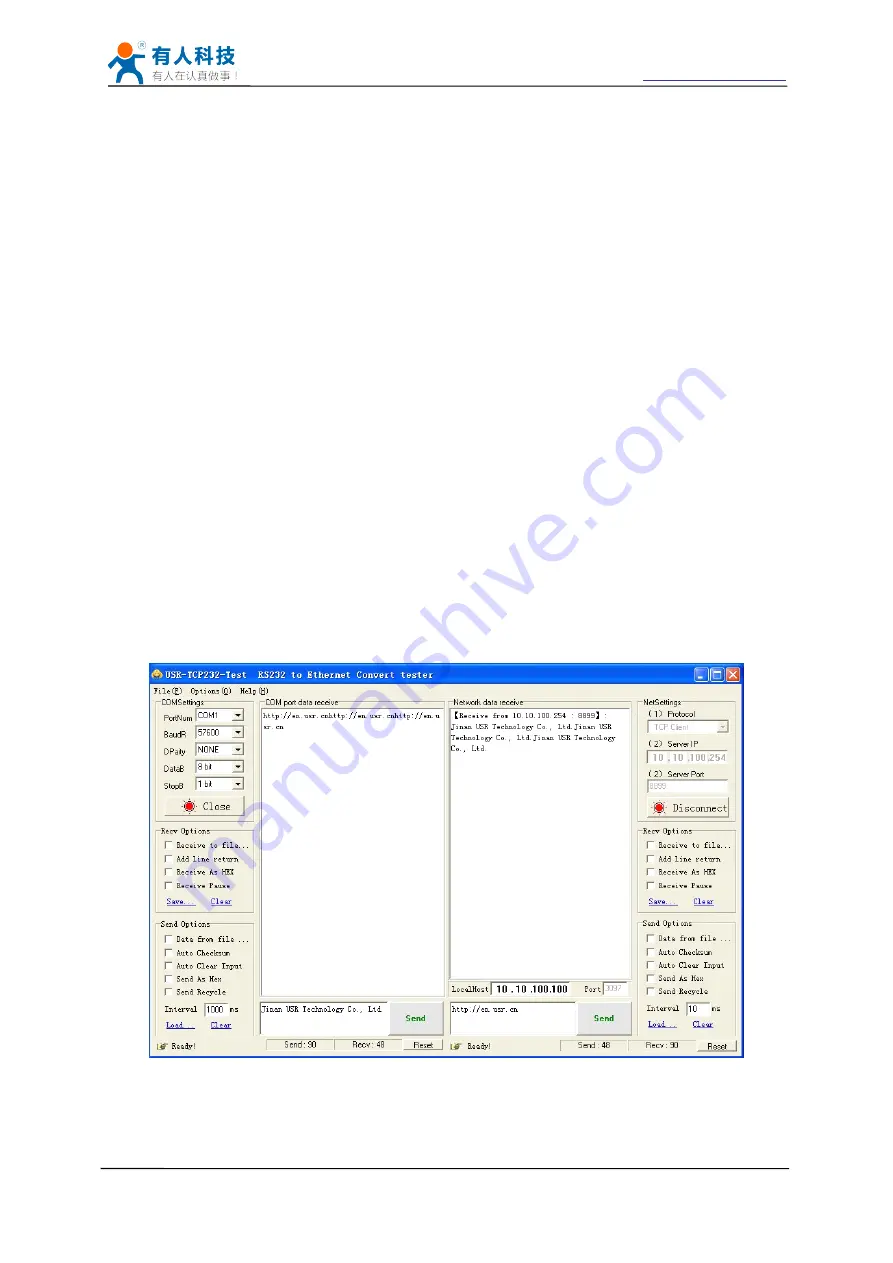
We just need to follow the parameters of the corresponding set of network communication
parameters, you can make serial <--> WIFI communication, the steps are as follows:
1.
Open test software USR-TCP232-Test;
2.
COM Settings area (left):
Choose COM port witch has connect the module, there is COM3, choose band rate to 57600, this
is the default band rate of WIFI module, Click Open COM port.
3.
Net Settings area (right):
Choose TCP client mode, Server IP write 10.10.100.254, it is the WIFI default IP address, Server
port to 8899, It is the default Port the WIFI module listen, Click Connect to link to the module.
Now, you can test send data between RS232 and WIFI.
COM port to WIFI: PC RS232 -> Module RS232 -> Module WIFI -> PC WIFI.
WIFI to COM port: PC WIFI -> Module WIFI -> Module RS232 -> PC RS232.
Figure 4
serial
serial
serial
serial //// network
network
network
network transmission
transmission
transmission
transmission test
test
test
test


