User’s Manual
6
2.1 Introduction
The following sections show the internal jumper settings and the external connectors and pin assignments for
applications.
2.2 Jumpers and connectors
The PMI-3110 Embedded Box Computer consists of an JHC SBC (Single Board Computer) board that is
housed in an aluminum plate chassis. Your HDD and SDRAM, are all readily accessible by removing the
aluminum bottom cover. Any maintenance or hardware upgrades can be easily completed after removing the
bottom cover.
Warning:Do not remove any mechanical parts until you have verified that no power is flowing within the
Embedded Box Computer. Power must be switched off and the power cord must be unplugged.
2.2.1 Setting Jumpers
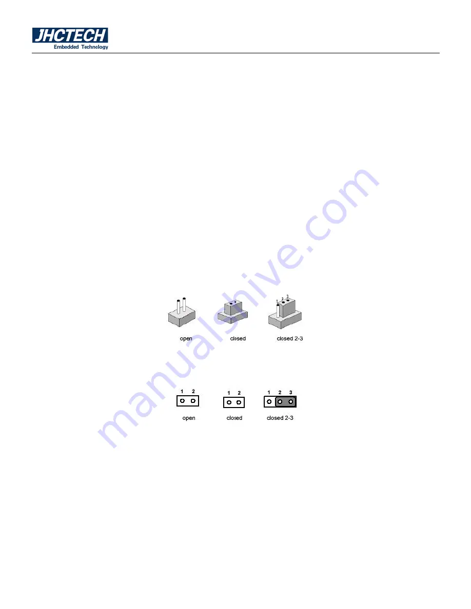
You can configure your PMI-3110 to match the needs of your application by setting the jumpers. A jumper is
the simplest kind of electrical switch. It consists of two metal pins and a small metal clip (often protected by
a plastic cover) that slides over the pins to connect them. To —close“ a jumper, you connect the pins with the
clip. To —open“ a jumper you remove the clip. Sometimes a jumper will have three pins, labeled 1, 2, and 3.
In this case, you would connect either pins 1 and 2 or pins 2 and 3.
Figure 2.1
The jumper settings are schematically depicted in this manual as follows:
Figure 2.2
A pair of needle-nose pliers may be helpful when working with jumpers. If you have any doubts about the
best hardware configuration for your application, contact your local distributor or sales representative before
you make any changes.
2.3 Jumper Location
The PMI-3110 Embedded Box Computer has a number of jumpers inside the chassis that allows you to
configure your system to suit your application. The table below lists the functions of the various jumpers.
The table below shows the function of each of the board's jumpers:
Содержание PMI-3110
Страница 8: ...User s Manual 1 General Information CHAPTER 1 ...
Страница 11: ...User s Manual 4 PMI 3110 S002 Dimensions Figure 1 1 ...
Страница 12: ...User s Manual 5 Hardware Installation CHAPTER 2 ...
Страница 14: ...User s Manual 7 Figure 2 3 ...
Страница 23: ...User s Manual 16 BIOS Setup CHAPTER 3 ...
Страница 38: ...User s Manual 31 Driver Installation CHAPTER 4 ...


