User’s Manual
36
3.1 Overview
The BIOS is a program that takes care of the basic level of communication between the CPU
and peripherals. It contains codes for various advanced features found in this system board.
The BIOS allows you to configure the system and save the configuration in a battery-backed
CMOS so that the data retains even when the power is off. In general, the information stored
in the CMOS RAM of the EEPROM will stay unchanged unless a configuration change has been
made such as a hard drive replaced or a device added.
It is possible that the CMOS battery will fail causing CMOS data loss. If this happens, you need
to install a new CMOS battery and reconfigure the BIOS settings.
3.2 Default Configuration
Most of the configuration settings are either predefined according to the Load Optimal Defaults
settings which are stored in the BIOS or are automatically detected and configured without
requiring any actions. There are a few settings that you may need to change depending on
your system configuration.
3.3 Entering the BIOS Setup Utility
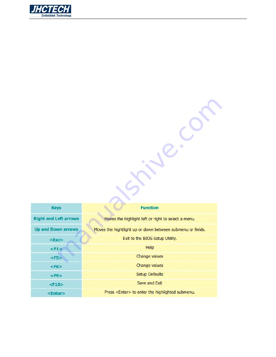
The BIOS Setup Utility can only be operated from the keyboard and all commands are keyboard
commands. The commands are available at the right side of each setup screen.
The BIOS Setup Utility does not require an operating system to run. After you power up the
system, the BIOS message appears on the screen and the memory count begins. After the
memory test, the message ―Press DEL to run setup‖ will appear on the screen. If the message
disappears before you respond, restart the system or press the ―Reset‖ button. You may also
restart the system by pressing the <Ctrl> <Alt> and <Del> keys simultaneously.
3.4 Legends
3.5 Scroll Bar
When a scroll bar appears to the right of the setup screen, it indicates that there are more
available fields not shown on the screen. Use the up and down arrow keys to scroll through all
the available fields.
Содержание ALAD-A1201T
Страница 2: ...User s Manual 2 Version Note No Ver Note Date Writer 1 A1 0 first publish 20160718 Colin Cheng ...
Страница 8: ...User s Manual 1 General Information CHAPTER 1 ...
Страница 11: ...User s Manual 4 EMC CE FCC Class A 1 5 Mechanical Specifications ALAD A1201T Dimensions Uint mm Figure 1 1 ...
Страница 12: ...User s Manual 5 Hardware Installation CHAPTER 2 ...
Страница 19: ...User s Manual 12 2 4 I O indication Front view Rear view Figure 2 11 ...
Страница 25: ...User s Manual 18 Figure 2 22 Figure 2 23 ...
Страница 32: ...User s Manual 25 Figure 2 35 Figure 2 36 ...
Страница 36: ...User s Manual 29 Step 2 Aligning the I O cover at the I O opening note the key holes Figure 2 43 Figure 2 44 ...
Страница 38: ...User s Manual 31 Figure 2 47 Step 2 Plug USB device into the USB type A connector Figure 2 48 ...
Страница 39: ...User s Manual 32 2 5 6 Panel Mounting Step 1 Install the panel PC into the panel opening Figure 2 49 ...
Страница 41: ...User s Manual 34 Step 3 Insert the screws into each clamp and fasten them Figure 2 52 ...
Страница 42: ...User s Manual 35 BIOS Setup CHAPTER 3 ...
Страница 52: ...User s Manual 45 Figure 3 11 PCI Express Configuration Figure 3 12 PCI Express Root Port ...
Страница 58: ...User s Manual 51 Figure 3 20 USB Boot 3 12 Exit Figure 3 21 Exit ...
Страница 60: ...User s Manual 53 Driver Installation CHAPTER 4 ...
Страница 64: ...User s Manual 57 SYSTEM RESOURCE CHAPTER 5 ...
Страница 65: ...User s Manual 58 5 1 WDT Function WDT Set Example See the function WD_SetTimerValue ucResetTime ...


