


PDL5 User Manual
PDL5-UM-00001 Rev 001
21
Measuring BR (Excluding the Connector)
The method described in the “MEASURING BR (Including Connector)” section is
used to measure the backreflection if the DUT is a connector, or if the DUT is a
connectorized component and the total backreflection from the connector and
the DUT is desired.
It is sometimes desirable to know the backreflection of a connectorized DUT,
but excluding the connector. If the fiber type is single-mode, this is possible, but
a few extra steps must be taken for every measurement to reference out the
connector (i.e., the user must do a BR
0
for every DUT).
Refer to the “MEASURING BR (Including Connector)” section and redo the BR
0
measurements for each wavelength, but this time, when terminating between
the DUT’s connector and the DUT. Note that if a BR
0
value has already been
stored, it is required to press the BR
0
button first, to erase it and then press it
again to store the new value.
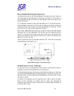
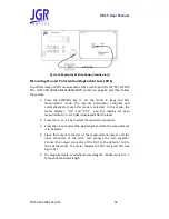
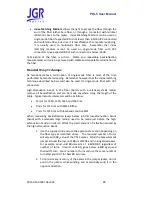
Create a termination point on the pigtail after the DUT. The meter now displays
the backreflection of the DUT only.
Figure 8: Measuring BR
–
Excluding Connector
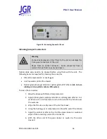
Backreflection Accuracy and Range
The absolute accuracy of backreflection measurements made with the meter is
dependent on the level of backreflection to be measured.
The backreflection measurement range is restricted by the BR
0
level. The meter
can measure backreflection levels 15 dB below BR
0
to a maximum of -80 dB. For
example, if BR
0
is -40 dB, the minimum backreflection of the DUT that can be
measured is -55 dB.
An asterisk (*) is displayed near the range limit (last 5 dB of range if using BR
0
,
below -60 dB otherwise) to indicate that the setup and measurement
procedures described in the previous two sections must be followed carefully to
ensure accurate results.