JF-Stoll GX 3202 SM Скачать руководство пользователя страница 20

3. ADJUSTMENTS AND DRIVING 

PIGB-093X-06 GX 2402/2802/3202 SM-GX 2402/2802 SC  0410 

20 


P

R

14

-0054

A

Fig. 3-1 

Fig. 3-2 

P

R

14-005

3

B

Fig. 3-3 

Fig. 3-4 

Fig. 3-5 

Fig. 3-6 

Содержание GX 3202 SM

Страница 1: ...Disc Mower GX 2402 SM SC I GX 2802 SM SC I GX 3202 SM Instruction Manual Original instructions Edition 6 I April 2010...

Страница 2: ...pe GX 2402 SM FR Mod le GX 2802 SC ES modelo GX 2802 SM PT Marca GX 3202 SM DA Typ PL Model FI Merkki EN ES DE PT IT DA NL PL FR FI to which this declaration relates corresponds to the relevant basic...

Страница 3: ...tion manual very carefully before using the machine Pay special attention to the safety instructions This instruction manual is made so that the information is mentioned in the order you will need it...

Страница 4: ...3 ADJUSTMENTS AND DRIVING 21 CONNECTION 21 SWITCHING BETWEEN WORKING AND TRANSPORT POSITION 21 PARKING 23 WORKING IN THE FIELD 23 Basic adjustments 23 Stubble height 23 Starting 23 Turning 25 The brea...

Страница 5: ...N GENERAL 43 FRICTION CLUTCH 45 CONTROL OF BALANCE 45 CUTTER BAR DISCS AND BLADES 47 Blades 47 Replacement of blades 49 Cutter bar and discs 49 CONDITIONER 51 Tightening of roller chain 51 WINTER STOR...

Страница 6: ...risk If changes are made on the machine and its construction without permission from JF Fabriken A S JF Fabriken A S cannot be held responsible for any damage resulting from this Intended use of cours...

Страница 7: ...o others before you have made sure that they have the necessary knowledge to operate the machine safely DEFINITIONS The safety decals and the instruction manual of the machine contain a line of safety...

Страница 8: ...9 When connecting the PTO drive shaft check for 540 1000 rpm 10 Never start the tractor until all persons are safely away from the machine 11 Do not stand near the machine while it is working 12 Stop...

Страница 9: ...stake It is highly dangerous to connect a machine intended for 540 rpm to a PTO delivering 1000 rpm Long term overload may damage the machine and at worst result in ejection of parts Choose a tractor...

Страница 10: ...ents To ensure all the air has been expelled from the oil in the hydraulic cylinders test all the functions after the hydraulic connections are connected to the tractor Especially before driving on pu...

Страница 11: ...ightened to the correct torque When replacing parts in the hydraulic system always make sure that the cutting unit rests on the ground or the lifting cylinders are blocked Hydraulic hoses must be chec...

Страница 12: ...1 INTRODUCTION PIGB 093X 06 GX 2402 2802 3202 SM GX 2402 2802 SC 0410 12 2 1 2 3 4 5 6 7 8 9 10 11 12 12 1 3 4 5 6 STOP 2 MIN 7 8 9 10 11 12 Min 10 m...

Страница 13: ...6 Children Never let children stand near the machine during operation Especially not small children as they have a tendency to do unforeseen things 7 Momentum After the PTO drive shaft has stopped th...

Страница 14: ...riable stubble height mm 45 90 45 90 Swath width interval m 1 0 2 2 1 2 2 6 Transport width m 3 3 Type Rubber rollers Chevron Rubber rollers Chevron Conditioner Speeds rpm 1000 1000 Stone release mech...

Страница 15: ...45 90 45 90 Swath width interval m 1 0 2 4 1 2 2 8 1 4 3 2 Transport width m 3 3 3 Type PE fingers PE fingers PE fingers Condition er Speeds rpm 700 860 Standard 700 860 Standard 700 860 Standard Wid...

Страница 16: ...CONNECTION AND TEST DRIVING PIGB 093X 06 GX 2402 2802 3202 SM GX 2402 2802 SC 0410 16 P R 1 1 0 3 3 3 a A D D B C Fig 2 1 Fig 2 2 PR12 0257a F I Fig 2 3 Fig 2 4 PR14 0053 B A B PR12 1192 Fig 2 5 Fig 2...

Страница 17: ...when lifting the machine with the link arms and optimal conditions for later connection and disconnection of the machine Fig 2 4 Connect the hydraulic hoses to a double acting hydraulic outlet Place t...

Страница 18: ...2 CONNECTION AND TEST DRIVING PIGB 093X 06 GX 2402 2802 3202 SM GX 2402 2802 SC 0410 18 PR12 1169 B PR11 5017 Fig 2 7 Fig 2 8 PR12 1168 C B A D 100 Fig 2 9 Fig 2 10...

Страница 19: ...st be dismounted After this the tubes are greased by disassembling the 2 half parts IMPORTANT For the warranty of the PTO shaft to be valid and to retain the durability the following rules must be obs...

Страница 20: ...3 ADJUSTMENTS AND DRIVING PIGB 093X 06 GX 2402 2802 3202 SM GX 2402 2802 SC 0410 20 PR14 0054 A Fig 3 1 Fig 3 2 PR14 0053 B Fig 3 3 Fig 3 4 Fig 3 5 Fig 3 6...

Страница 21: ...outlet SWITCHING BETWEEN WORKING AND TRANSPORT POSITION Fig 3 4 The transport lock B is released for working position and locked for transport position WARNING Conversion to transport position should...

Страница 22: ...3 ADJUSTMENTS AND DRIVING PIGB 093X 06 GX 2402 2802 3202 SM GX 2402 2802 SC 0410 22 PR12 1192 A B PR14 0053 B Fig 3 7 Fig 3 8 Fig 3 9...

Страница 23: ...ne is constructed to cut with a theoretical cutting height from 22 mm to 45 mm This means that the real stubble height will be from approximately 45 mm to 90 mm Usually the stubble height is 2 x theor...

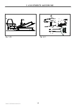
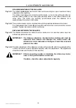
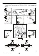
Страница 24: ...3 ADJUSTMENTS AND DRIVING PIGB 093X 06 GX 2402 2802 3202 SM GX 2402 2802 SC 0410 24 PR12 0018 Fig 3 10 Fig 3 11...

Страница 25: ...r tighten the spring so much that it blocks the mechanism due to insufficient spring travel SECURING AGAINST OVERLOAD IMPORTANT The tractor driver can secure the transmission against overload When usi...

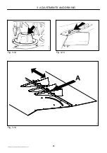
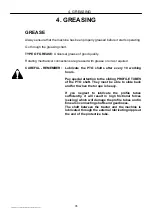
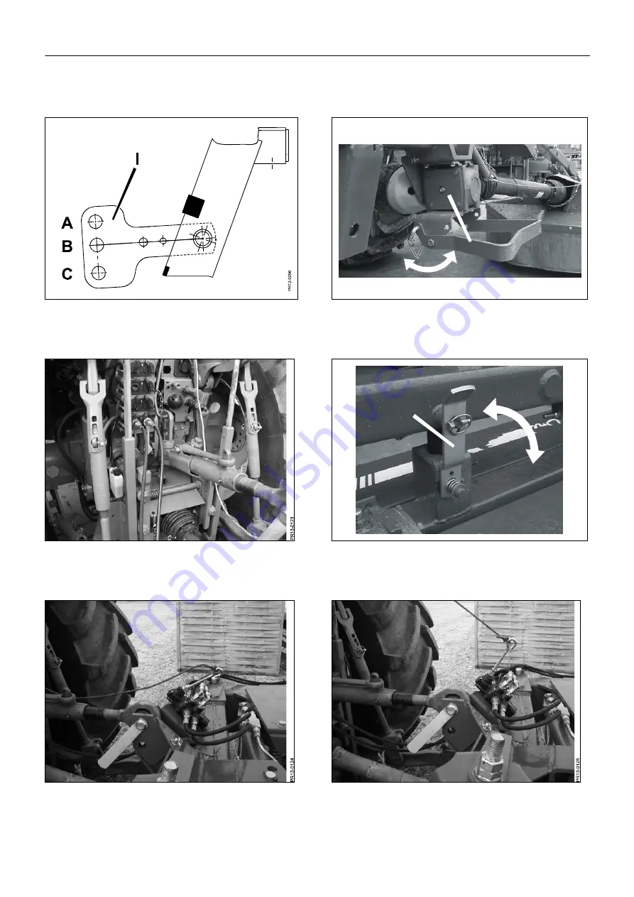
Страница 26: ...3 ADJUSTMENTS AND DRIVING PIGB 093X 06 GX 2402 2802 3202 SM GX 2402 2802 SC 0410 26 Fig 3 12 Fig 3 13 Fig 3 14...

Страница 27: ...king up for a forage harvester or a baler Fig 3 13 The width of the swath can be adjusted by turning the swath guards The bolts handles on the top plate are loosened and the guards are moved either ou...

Страница 28: ...3 ADJUSTMENTS AND DRIVING PIGB 093X 06 GX 2402 2802 3202 SM GX 2402 2802 SC 0410 28 Fig 3 15 Fig 3 16 PR12 0646 E D Fig 3 17...

Страница 29: ...fingers C on the rotor The shorter the distance the stronger the conditioning of the crop Fig 3 17 The system is operated with the handle D which can be placed in 3 positions on the bracket E The dist...

Страница 30: ...3 ADJUSTMENTS AND DRIVING PIGB 093X 06 GX 2402 2802 3202 SM GX 2402 2802 SC 0410 30 PR12 0991 A Fig 3 18 Fig 3 19 Fig 3 20...

Страница 31: ...s held in the hand The reason may be that the roller distance is too long that the roller pressure is too low and that the driving speed is too high It may be difficult to make out whether the conditi...

Страница 32: ...3 ADJUSTMENTS AND DRIVING PIGB 093X 06 GX 2402 2802 3202 SM GX 2402 2802 SC 0410 32 PR11 1052 X X PR12 0991b Fig 3 21 Fig 3 22 PR11 1053 2 mm PR12 0991a Fig 3 23 Fig 3 24...

Страница 33: ...ion Tighten the bolts to 200 Nm 20 kpm DISTANCE BETWEEN THE ROLLERS Fig 3 23 The distance between the rollers must be minimum 2 mm and the rollers must run without any particular noise IMPORTANT The d...

Страница 34: ...ype GX SM and SC The below grease spots must be greased according to the operation time intervals indicated PR11 0976 1 1 2 2 8 h 40 h 8 h 40 h PR11 0992 GX SC PR11 0991 GX SC GX SM GX SM PIGB 093X 06...

Страница 35: ...ng hours Pay special attention to the sliding PROFILE TUBES of the PTO shaft They must be able to slide back and forth when the torque is heavy If you neglect to lubricate the profile tubes sufficient...

Страница 36: ...4 GREASING PIGB 093X 06 GX 2402 2802 3202 SM GX 2402 2802 SC 0410 36 PR12 0407 D D Fig 4 1 Fig 4 2 Fig 4 3 Fig 4 4...

Страница 37: ...mm Average value This oil level must be an average of the level measured at both filling holes When the oil level has been checked wait 3 minutes if the oil is warm and check again If the oil is cold...

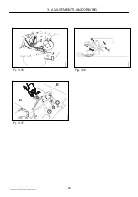
Страница 38: ...4 GREASING PIGB 093X 06 GX 2402 2802 3202 SM GX 2402 2802 SC 0410 38 Fig 4 5 Fig 4 6...

Страница 39: ...heating which in the long term will damage the bearings BEVEL GEARBOX ABOVE THE CUTTER BAR Fig 4 5 Oil content 0 9 l Oil type API GL4 or GL5 SAE 80W 90 Oil level n Check the oil level after every 80 h...

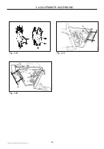
Страница 40: ...4 GREASING PIGB 093X 06 GX 2402 2802 3202 SM GX 2402 2802 SC 0410 40 PR11 0045 E Fig 4 7 Fig 4 8...

Страница 41: ...s could block the oil supply Turn on the oil when starting the machine by turning the tap at F until it is approximately half open IMPORTANT Remember to turn off the tap taps again when stopping the m...

Страница 42: ...M 12 80 120 135 M 12x1 25 90 125 146 M 14 135 180 215 M 14x1 5 145 190 230 M 16 200 280 325 M 16x1 5 215 295 350 M 18 270 380 440 M 20 400 550 650 M 20x1 5 430 615 720 M 24 640 900 1100 M 24x1 5 690 9...

Страница 43: ...if mounted and the machine according to the GENERAL SAFETY INSTRUCTIONS items 1 20 in the beginning of this instruction manual IMPORTANT Screws and bolts on your new machine must be retightened after...

Страница 44: ...5 MAINTENANCE PIGB 093X 06 GX 2402 2802 3202 SM GX 2402 2802 SC 0410 44 Fig 5 2 PR12 0709 A B D C Fig 5 3...

Страница 45: ...instruction manual for the PTO drive shaft delivered by the supplier IMPORTANT The outer metal band C indicates whether the tightening of the springs is correct Tighten the bolts D just so much that...

Страница 46: ...5 MAINTENANCE PIGB 093X 06 GX 2402 2802 3202 SM GX 2402 2802 SC 0410 46 Fig 5 4 Fig 5 5 PR12 1193 G H PR12 0040 I Fig 5 6 Fig 5 7 Fig 5 8 Fig 5 9...

Страница 47: ...e bolts and blades are made of high alloyed hardened materials This heat treatment provides especially hard and ductile material which is able to withstand extreme stress If a blade or a disc is damag...

Страница 48: ...5 MAINTENANCE PIGB 093X 06 GX 2402 2802 3202 SM GX 2402 2802 SC 0410 48 Fig 5 10 Fig 5 11 Fig 5 12 Fig 5 13 PR11 1194 90 Fig 5 14 Fig 5 15...

Страница 49: ...and sharp Replacement of blades is made by dismounting the blade bolt and pull it out from beneath the disc This is easily done when the blade is in the front position so that the bolt can fall out th...

Страница 50: ...5 MAINTENANCE PIGB 093X 06 GX 2402 2802 3202 SM GX 2402 2802 SC 0410 50 Fig 5 16 Fig 5 17 Fig 5 18...

Страница 51: ...to get out of balance which for instance will result in reduced life of the bearings TIGHTENING OF ROLLER CHAIN Fig 5 18 Press the sprocket wheel Z down towards the chain and tighten it WINTER STORAG...

Страница 52: ...onditioner fingers may be worn or missing The distance between the conditioner plate and the conditioner rotor is too long Replace worn fingers and mount new ones where these are missing Adjust the co...

Страница 53: ...on the first page in the spare parts book supplied with the machine as soon as possible so that you have the information at hand when ordering spare parts PR11 0344 MACHINE DISPOSAL When the machine...

Страница 54: ......

Страница 55: ...such as expenses for oil grease and minor adjustments 2 Transport of machine to and from workshop 3 The dealer s travelling expenses or freight charges to and from the user Warranty is not granted on...

Страница 56: ...of experience from right around the world and more importantly unique regional requirements We also receive important inspiration in our development work through a close and continuous dialogue with...

Отзывы: