background image

©2013-2016 Jewett-Cameron Company • www.jewettcameron.com •

 Customer Service: 800-955-2879

03-AG1-CONTRACTOR    2016-10-21

3

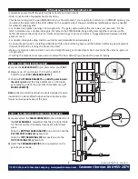
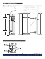
  STEP 2C: LATCH SIDE OF FRAME (A) INSTALLATION  

Carefully add the LATCH SIDE OF THE FRAME (A)
Now, carefully (at this point the frame is still loose) extend 
the gate frame to within 1 inch of the post where the latch 
will be attached.
Now measure the distance between the plates where the 
2x4’s will attach (top and bottom of frame), cut 2x4’s and 
attach using 1 INCH ROUNDHEAD WOOD SCREWS (G) for the 
plates, and 2 INCH FLATHEAD WOOD SCREWS (H) for the 
spreader bars.

NOTE:


Depending on the width of your gate, you may not 

need all of the 2 inch wood screws, it is not necessary to have 
a screw in every hole. Because it is an adjustable frame, not 
all the pre-drilled holes on the spreader bars and vertical 
frame sides will line up.

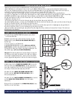
  STEP 3: TRUSS CABLE and GATE LATCH INSTALLATION

Be sure to loosen the TURNBUCKLE to its widest opening 

prior to assembly.

Assemble TRUSS CABLE as shown.
Slide the “S” HOOK of the TRUSS CABLE KIT (C) into the 

hole at the 

lower corner of the latch side of the gate frame.

Hook the TURNBUCKLE into the hole at the 

opposite top 

corner on the hinge side of the frame.

Form a loop on the loose end of the cable, thread through 

the CABLE CLAMP, slip that loop onto the “S” HOOK and 

pull cable tight, secure with clamp, cut off any excess.
Attach STRIKER BAR from the Gate Latch Kit (F) to the 

inside gate frame at the desired height use the 4 HEX HEAD 

SELF-TAPPING SCREWS (I) . Align the LATCH with the Striker 

Bar and attach to post using 1.5 INCH ROUNDHEAD WOOD 

SCREWS (K).

By adjusting the TURNBUCKLE you can fine tune the gate 

latch to give a perfect fit.

1”

2x4’s Not Included

2x4’s Not Included

2x4’s Not Included

F

C

I

K

G

H

A

G

G

H

G

Содержание Adjust-A-Gate AG36-3

Страница 1: ... 2 in Spade 5 16 Nut Driver Power Drill PARTS LIST 2x4 s Not Included A A B B F I H H H H H H 2x4 s Not Included C H H G G D CONTRACTOR SERIES H H A 2 60 in GATE FRAME SIDES B 2 SPREADER BARS 1 in x 1 in x 36 in for AG36 3 1 in x 1 in x 48 in for AG60 3 C 1 TRUSS CABLE KIT D 2 GATE FRAME HINGES with bolt and nut E 2 POST HINGES F 1 GATE LATCH KIT G 24 1 ROUNDHEAD WOOD SCREWS for 2x4 clips H 10 2 F...

Страница 2: ...frame into itself Make sure all 4x4 s posts and 2x4 s rails are straight bowing or crooked 4x4 2x4 s may make the adjust a gate out of alignment If cutting the spreader bars spray all cut ends with a Rust Oleum type product to prevent rusting GETTING READY TO ASSEMBLE YOUR GATE KIT STEP 1 POST HINGE E INSTALLATION A Locate the CENTER POINT top to bottom on your POST B Measure up 20 and down 20 to ...

Страница 3: ...s on the spreader bars and vertical frame sides will line up STEP 3 TRUSS CABLE and GATE LATCH INSTALLATION Be sure to loosen the TURNBUCKLE to its widest opening prior to assembly Assemble TRUSS CABLE as shown Slide the S HOOK of the TRUSS CABLE KIT C into the hole at the lower corner of the latch side of the gate frame Hook the TURNBUCKLE into the hole at the opposite top corner on the hinge sid...

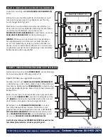
Страница 4: ... this gap APPLICABLE TO INWARD SWINGING GATES ONLY TIP It is recommended that your gate boards be cut 2 shorter than the fence boards to allow the top of your gate to be even with the fence and allow clearance under the gate Now you can attach the rest of your boards onto the 2x4 s on the gate using nails or screws By adjusting the tunbuckle on the truss cable you can fine tune the gate LATCH CATC...

Страница 5: ... H H H H H H C H H G G D NE H H Kniptang 1 2cm inch steel 8mm schroefkop boormachine 3 8x8 9cm Niet meegeleverd A 2 1 52M ZIJKANTEN VAN HET POORTFRAME B 2 SPREIDBALKEN 2 5 x 2 5 x 91 4cm for AG36 3 2 5 x 2 5 x 122cm for AG60 3 C 1 SPANKABELSET D 2 POORTRAME SCHARNIEREN Met bouten en moeren E 2 POORTSCHARNIEREN F 1 POORTKLINK SET G 24 2 5cm RONDKOPSCHROEVEN VOOR HOUT voor klemmen H 10 5cm PLATTE HO...

Страница 6: ...ls recht zijn verbogen of kromme 8 9x8 9cm 3 8x8 9cm kunnen ervoor zorgen dat de adjust a gate niet uitgelijnd is Als u de spreidbalken afknipt moet u alle uiteinden inspuiten met een Rust Oleum type product om roesten te voorkomen VOORBEREIDING OP DE MONTAGE VAN UW POORT STAP 1 INSTALLATIE VAN HET PAALSCHARNIER E A Zoek het MIDDELPUNT van boven naar beneden op uw PAAL B Meet 51cm omhoog en omlaag...

Страница 7: ...n van het frame op elkaar aansluiten STAP 3 INSTALLATIE VAN DE SPANKABEL en POORTKLINK Zorg ervoor dat de SPANSCHROEF zo ver mogelijk geopend is voordat u begint met de montage Monteer de SPANKABEL zoals getoond wordt Schuif de S HAAK van de SPANKABELSET C in het gat in de benedenhoek van de klinkzijde van het poortframe Haak de SPANSCHROEF in het gat van de tegenoverliggende bovenhoek van de klin...

Страница 8: ...OEPASSING OP POORTEN DIE NAAR BINNEN OPENEN TIP wij adviseren u om de planken van de poort 5cm korter te zagen dan de planken van de schutting zodat de bovenkant van uw poort gelijk komt met de schutting en er een uitsparing komt onder de poort U kunt nu de rest van uw planken aan de 3 8x8 9cm van de poort bevestigen met behulp van spijkers of schroeven Door de spanschroef van de spankabel aan te ...

Страница 9: ...mécanique LISTE DES PIÈCES A A B B F I H H G G H H C H H H H D F H H Colombages 3 8x8 9cm non inclus Colombages 3 8x8 9cm non inclus A 2 MONTANTS DE PORTE de 1 52m B 2 BARRES D ÉCARTEMENT 2 5 x 2 5 x 92 cm AG36 3 2 5 x 2 5 x 122cm AG60 3 C 1 ENSEMBLE DE TREILLIS D 2 CHARNIÈRES POUR LE CHÂSSIS DE LA PORTE avec boulon et écrou E 2 CHARNIÈRES POUR POTEAU F 1 LINGUET POUR LA PORTE G 24 2 5cm VIS À BOI...

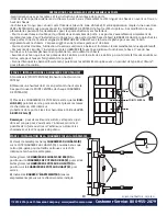
Страница 10: ... 8 9x8 9cm po et les rails de 3 8x8 9cm po sont droits s ils sont courbés ou tordus cela peut fausser l alignement de la porte Si vous découpez les barres d écartement pulvérisez les extrémités coupées avec un produit de type Rust Oleum pour prévenir la rouille PRÉPARATION À L ASSEMBLAGE DE VOTRE ENSEMBLE DE PORTE ÉTAPE 1 INSTALLATION DE LA CHARNIÈRE DE POTEAU E A Localisez le POINT CENTRAL de hau...

Страница 11: ...ÊTE HEXAGONALE I Alignez le LINGUET avec la barre de gâche et fixez à l aide des VIS À BOIS 5CM À TÊTE RONDE K Vous pouvez régler le linguet de la porte avec précision en réglant le TENDEUR 1 F C I K G H A G G H G A Ajoutez le CÔTÉ LINGUET DU CHÂSSIS A avec précaution Ensuite avec précaution à ce stade le châssis n est pas encore fixe approchez la porte à 2 5cm du poteau auquel elle sera fixée Mes...

Страница 12: ...ES S OUVRANT VERS L INTÉRIEUR UNIQUEMENT CONSEIL il est recommandé que vos planches de portes soient plus courtes de 5cm que les planches de la clôture afin que la partie supérieure de la barrière soit au même niveau que la clôture et qu il y ait un espace sous la porte Vous pouvez maintenant fixer le reste de vos planches sur les planches de 3 8x8 9 po de la porte à l aide de vis ou de clous Vous...

Страница 13: ...r 8 mm Steckschlüssel Bohrmaschine STÜCKLISTE A A B B F I H H G G H H C H H H H D Bauholz 3 8 x 8 9cm nicht inbegriffen Bauholz 3 8 x 8 9cm nicht inbegriffen D H H A 2 TORRAHMEN SEITEN 1 52m B 2 SPREIZSTANGEN 2 5 x 2 5 x 92 cm AG36 3 2 5 x 2 5 x 122cm AG60 3 C 1 DRAHTSEIL SPANNER D 2 TORRAHMEN SCHARNIERE mit Schraube und Mutter E 2 PFOSTENGELENKE F 1 TORSCHLOSS SATZ G 24 2 5cm RUNDKOPF HOLZSCHRAUB...

Страница 14: ...chienen führen zu einer Fehlstellung des Adjust A Gate Beim Schneiden der Spreizstangen besprühen Sie alle abgeschnittenen Enden mit einem Rust Oleum Produkt um Rostbildung zu verhindern VORBEREITUNG DER MONTAGE IHRES TOR BAUTEILS SCHRITT 1 MONTAGE DES PFOSTENGELENK E A Finden Sie den MITTELPUNKT von oben nach unten auf ihrem PFOSTEN B Messen Sie 51cm nach oben und nach unten um den Mittelpunkt fü...

Страница 15: ...ten Höhe und benutzen dazu die 4 SECHSKANT KOPF BLECHSCHRAUBEN I Richten Sie das Schloss mit dem STANGENTÜRSCHLIESSER aus und befestigen es mit den 3 8 cm RUNDKOPF HOLZSCHRAUBEN Holz K Durch die Einstellung des SPANNSCHLOSSES können Sie das Torschloss feineinstellen damit es perfekt passt 1 F C I K G H A G G H G Fügen Sie vorsichtig die SCHLOSSSEITE DES RAHMENS A hinzu Ziehen Sie nun vorsichtig je...

Страница 16: ...WINGENDE TORE TIPP Es wird empfohlen Ihre Torlatten 5 cm kürzer zuzus chneiden als die Zaunlatten damit die obere Seite des Tors bündig mit dem Zaun abschließt und genug Bodenab stand unter dem Tor vorhanden ist Jetzt können Sie den Rest Ihrer Latten mit Nägeln oder Schrauben auf den 3 8 x 8 9 cm Brettern am Tor befestigen Durch Anpassen des Spannschlosses am Drahtseilkabel können Sie die Feineins...

Страница 17: ...Punta a lancia da 1 25cm Chiave a brugola da 8mm Trapano Assi 3 8x8 9cm cm non incluse Assi 3 8x8 9 cm non incluse A 2 LATI TELAIO CANCELLO da 1 52m B 2 BARRE DISTANZIATRICI 2 5 x 2 5 x 92 cm for AG36 3 2 5 x 2 5 x 122cm for AG60 3 C 1 KIT CAVI TENDITORI D 2 CERNIERE TELAIO CANCELLO Con viti e dadi E 2 CERNIERE PILASTRO F 1 KIT CHIAVISTELLO G 24 VITI PER LEGNO A TESTA TONDA 2 5 CM Per ganci H 10 V...

Страница 18: ...B Inserire le BARRE DISTANZIATRICI B negli appositi incavi nel telaio del cancello come mostrato E J B D B 51cm 51cm Familiarizzate con i componenti del telaio e con le istruzioni Questo telaio è progettato per aprirsi verso l INTERNO nella vostra area recintata nel caso fosse richiesta l apertura verso l ESTERNO è possibile modificare il posizionamento delle CERNIERE SUL PILASTRO sul lato opposto...

Страница 19: ...tanziatrici e sui lati verticali del telaio saranno allineati PASSO 3 INSTALLAZIONE CAVO TENDITORE E CHIAVISTELLO Assicurarsi che il TENDITORE sia aperto al massimo possibile prima di procedere col montaggio Assemblare il CAVO TENDITORE come mostrato Infilare il GANCIO A S del KIT CAVO TENDITORE C nel foro nell angolo inferiore del telaio dal lato del chiavistello Agganciare il TENDITORE nel foro ...

Страница 20: ...SOLO AI CANCELLI CON APERTURA VERSO L INTERNO CONSIGLIO Raccomandiamo di tagliare le assi del cancello almeno 5 cm più corte delle assi della staccionata in modo da poter pareggiare il lato superiore del cancello lasciando uno spazio libero nel lato inferiore del cancello Ora è possibile fissare il resto delle assi sulla traversa 3 8x8 9 cm utilizzando chiodi o viti Regolando il tenditore è possib...

Страница 21: ...mm Taladro 3 8x8 9cm No Incluidos 3 8x8 9cm No Incluidos A 2 MARCOS LATERALES DE LA PUERTA DE 1 52m B 2 BARRAS DE SEPARACIÓN 2 5 x 2 5 x 92 cm para AG36 3 2 5 x 2 5 x 122cm para AG60 3 C 1 KIT DE CABLE DE CELOSÍA D 2 BISAGRAS DE MARCO DE PUERTA con perno y tuerca E 2 BISAGRAS PARA POSTE F 1 KIT DE CERROJO PARA PUERTA G 24 TORNILLOS DE 2 5cm CON CABEZA REDONDEADA PARA MADERA para clips de 2x4 H 10 ...

Страница 22: ...S SEPARADORAS B en el miembro de deslizamiento sobre el marco de la puerta como se muestra E J B D B 51cm 51cm Familiarizrse con los herrajes de los marcos de la puerta y las instrucciones Este marco está diseñado para abrir hacia ADENTRO en su área cercada si su aplicación requiere una abertura hacia AFUERA usted puede ajustar la colocación de las BISAGRAS DE POSTE al lado opuesto del poste Se pu...

Страница 23: ...NTES I Deberá alinear el CERROJO con la barra separadora y colocar en el poste utilizando los TORNILLOS DE CABEZA REDONDEADA PARA MADERA DE 3 8cm K Al ajustar el TENSOR puede ajustar con precisión el cerrojo de la puerta para conseguir un ajuste perfecto 1 F C I K G H A G G H G Añada cuidadosamente el MARCO LATERAL DE LA CERRADURA DE LA PUERTA A Ahora cuidadosamente en este punto el marco sigue es...

Страница 24: ...AS BASCULANTES HACIA ADENTRO CONSEJO Se recomienda cortar los paneles de su puerta 5cm más cortos que los paneles de la cerca para permitir que la parte superior de su puerta esté al mismo nivel que la cerca y deje un espacio libre por debajo de la puerta Ahora puede colocar el resto de los paneles sobre los 3 8x8 9cm en la puerta usando los tonillos o clavos Al ajustar el tensor en el cable de ce...

Отзывы: