background image

18

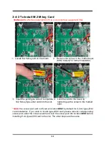
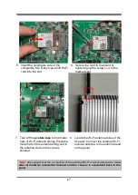
2-4-4 To Install M.2 B-key Card along with Nano-SIM card

M2B slot:

M.2 B-Key (3042/3052/6570) supports 3G/4G/5G module, co-function

with SIM card installed.

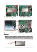
1) to install compatible SIM card into SIM card slot:

1. Locate SIM card slot on the board;

2. Use a pair of tweezers to pick up

compatible SIM card and push it into the

slot in the direction as shown.

3. The board with compatible SIM card

installed in place.

Содержание HPC150R-DCP6305E Series

Страница 1: ...Panel PC User s Manual NO G03 PCLZ0FRFP F Manual Revision 1 0 Release Date 2022 03 03...

Страница 2: ...r Settings 10 2 4 Hardware Installation 13 2 4 1 To Install SO DIMM to the Board 13 2 4 2 To Install M 2 M Key Card 14 2 4 3 To Install M 2 E Key Wi Fi Card 15 2 4 4 To Install M 2 B Key Card along wi...

Страница 3: ...Make sure to set up or use the product on a stable surface Make sure not to drop the product or strike it by any means Make sure not to move the product when the power is on Make sure not to step on t...

Страница 4: ...any kind and will not be liable for any indirect special incidental or consequential damages including damages for loss of profit loss of business loss of use of data interruption of business and the...

Страница 5: ...ice expansion 1 M 2 M key 2242 2280 PCIe 4 0 x4interface supports NVMe 1 M 2 E key 2230 USB2 0 PCIex1 interface supports CNVi 1 M 2 B key 3042 3052 6570 supports 3G 4G 5G Module 1 SIM card slot 2 Inte...

Страница 6: ...zel Display Type 15 0 with LED Backlight Brightness cd m 350 nits Display Color 16 7m display color Resolution 1024 x 768 60Hz Viewing Angle 178 178 H V Pixel Pitch 0 099 x 0 297mm Aspect Ratio 4 3 Co...

Страница 7: ...5 LAN 1 Intel I225V 2 5G 1 Intel I219LM GbE 1 12 36V DC in Locking Jack 1 Power button 1 2pin Front Power button Power Power Input 12 36V DC in AC version 100 240V AC DC 60W power adapter or DC versio...

Страница 8: ...system Power Button Jack For user to turn on off the system AT ATX Mode Switch AT ATX mode Supported at front side I O switch AT Directly PWR on as Power input ready ATX Press Button to PWR on after...

Страница 9: ...nector Description DCIN1 3 pin 12 36V DC in Power Connector Pin No Definition 1 12 36V VCC 2 GND 3 GND Warning Find Pin 1 position before connecting power cable to this 3 pin power connector WRONG INS...

Страница 10: ...NC NC 7 RTS NC NC 8 CTS NC NC 9 RI NC NC COM1 COM2 ports can function as RS232 422 485 port In normal settings COM1 COM2 functions as RS232 port With compatible COM cable they can function as RS422 or...

Страница 11: ...ack shell refer to 2 4 3 step 1 to make further settings on the daughter board for specific function User can set COM3 4 as GPIO port by setting up JP2 JP18 Pin 2 3 closed The pin assignment for GPIO...

Страница 12: ...8 Chapter 2 Hardware and Installation 2 1 Dimension and Outlines Measure Unit mm...

Страница 13: ...upon a stable platform with this side up Tighten up the screws in the marked spots to remove HDD and SO DIMM covers 2 User can install expansion parts according to their own needs DDR4 SO DIMMs M 2 M...

Страница 14: ...ove jumper clip from 2 jumper pins to open the pins Diagram 2 1 illustrates how to set up a jumper JP1 3 pin EDP BACKLIGHT VCC Select 2 0 pitch JP2 4 pin EPD Panel VCC Select 2 0 pitch JP2 EDP Panel V...

Страница 15: ...JPCOM1 2 4 pin COM1 COM2 Port Pin9 Function Select 2 0 pitch JPCOM1 COM1 Port Pin 9 JPCOM2 COM2 Port Pin 9 2 4 Closed PIN9 RS232 3 4 Closed PIN9 5V 4 6 Closed PIN9 12V 1 3 5 4 6 2 6 4 2 5 3 1 4 6 2 5...

Страница 16: ...JBAT 4 pin Clear CMOS Setting 2 0 pitch 3 4 Closed Clear CMOS 3 4 Open Normal Default PIN 3 4 Clear CMOS Pin1 2 Pin1 2 3 4 4 3 J80PORT 2 pin GPIO Select 2 0 pitch 1 2 Closed GPIO 1 2 Open 80 port Pin1...

Страница 17: ...gold figure side of a compatible SO DIMM into the slot at a 30 degree See to it that the break of the module fit into the notch of the slot and the golden finger side should be fully plugged into the...

Страница 18: ...compatible M 2 M key type 2242 card into the slot 4 Lock the card to the board by tightening up the screw to the marked spot Note the screw post and nut fixed at location MH2 by default for 4 2cm type...

Страница 19: ...responding metal button on the installed WiFi card so they need to remove the whole chassis heat sink shell on the back of the Panel PC for further installation which is different from 2 2 please refe...

Страница 20: ...ar off the acetate tape which protects the metal hats of the string end Notice The other wires cables must be wrapped with Insulated Tape and placed in the original position to avoid short circuit cau...

Страница 21: ...l hats of Wi Fi antenna strings Press the metal hats of the antenna string end to the antenna slots on the card as showed 8 Locate the Wi Fi antenna holes of the IO panel Connect the external Wi Fi re...

Страница 22: ...3G 4G 5G module co function with SIM card installed 1 to install compatible SIM card into SIM card slot 1 Locate SIM card slot on the board 2 Use a pair of tweezers to pick up compatible SIM card and...

Страница 23: ...in different lengths The installation steps are basically the same Take the installation process of type 3052 card as an example 1 Locate M 2 B key slot on the board 2 Remove the screw nut in the mar...

Страница 24: ...y emerged into the slot and then secure it by tightening the screws at locations MH3 MH4 Note In the case that compatible M2B card comes with metal buttons to be connected with antenna strings user ne...

Страница 25: ...HDD space Please refer to the following instructions and illustration to install a 2 5 SATA HDD Before installation 1 Locate the HDD connector onboard and prepare compatible 2 5 SATA hard disk 2 Inse...

Страница 26: ...ware device and configures the parameters of the hardware synchronization Only when these tasks are completed done it gives up control of the computer to operating system OS Since the BIOS is the only...

Страница 27: ...modify Press Enter to select Press keys when you want to modify the BIOS parameters for the active option F1 General help F2 Previous values F3 Optimized defaults F4 Save Exit Press Esc to exit from...

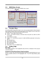
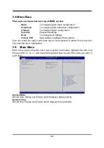
Страница 28: ...ting loading and exit options User can press the right or left arrow key on the keyboard to switch from menu bar The selected one is highlighted 3 6 Main Menu Main menu screen includes some basic syst...

Страница 29: ...ub items Intel VMX Virtualization The optional settings are Disabled Enabled When set as Enabled a VMM can utilize the additional hardware capabilities provided by Vanderpool Technology Intel R SpeedS...

Страница 30: ...ote In the case that user needs to update Me firmware user should set Me FW Image Re Flash as Enabled save the settings and exit The system will turn off and reboot after 4 seconds If the user goes to...

Страница 31: ...sabled Enabled Note This function is supported when ERP Support is set as Disabled USB S5 Power Use this item to enable or disable USB Power after System Shutdown The optional settings Disabled Enable...

Страница 32: ...de Speed Select Use this item to select RS232 RS422 RS485 Speed The optional settings RS232 RS422 RS485 250Kbps RS232 1Mbps RS422 RS485 10Mbps Serial Port 3 Configuration Press Enter to make settings...

Страница 33: ...o 255 minutes when WatchDog Reset Timer Unit set as Min WatchDog Reset Timer Unit The optional settings Sec Min Case Open Detect Use this item to detect case has already open or not show message in PO...

Страница 34: ...ort Console Redirection COM1 Console Redirection Use this item to enable or disable COM1 Console Redirection The optional settings Disabled Enabled When set as Enabled user can make further settings i...

Страница 35: ...ts indicate the end of a serial data packet A start bit indicates the beginning The standard setting is 1 stop bit Communication with slow devices may require more than 1 stop bit The optional setting...

Страница 36: ...n Console Redirection Settings page for more help with Terminal Type Emulation Bits per second EMS Use this item to select serial port transmission speed The speed must be matched on the other side Lo...

Страница 37: ...ements Network Stack Configuration Press Enter to go to Network Stack screen to make further settings Network Stack Use this item to enable or disable UEFI Network Stack The optional settings Disabled...

Страница 38: ...80 18bit Single 800x600 18bit Single 800x600 24bit Single 1024x600 18bit Single 1024x768 18bit Single 1024x768 24bit Single 1280x768 24bit Single 1280x800 18bit Single 1280x800 24bit Single 1366x768 1...

Страница 39: ...led Enabled Disabled HDA will be unconditionally disabled Enabled HAD will be unconditionally enabled System State After Power Failure Use this item to specify what state to go to when power is re app...

Страница 40: ...e new administrator password Secure Boot Press Enter to make customized secure settings System Mode Secure Boot Secure Boot feature is active if secure boot is enabled Platform Key PK is enrolled and...

Страница 41: ...image to run in Secure Boot mode Enroll SHA256 Hash certificate of a PE image into Authorized Signature Database db Device Guard Ready Remove UEFI CA from DB Restore DB default This item restore DB va...

Страница 42: ...abled Enabled Boot Option Priorities 3 11 Save Exit Menu Save Options Save Changes and Reset This item allows user to reset the system after saving the changes Discard Changes and Reset This item allo...

Страница 43: ...Fi Alliance Usage Environment and Your Health Wireless LAN PCI Express Mini Card emits radio frequency electromagnetic energy like other radio devices However the level of energy emitted is far much l...

Страница 44: ...imum exposure allowed by the Federal Communications Commission FCC This device complies with the limits for the Class B digital device pursuant to Part 15 subject to the following two conditions This...

Отзывы: