background image

1 Safety Instructions

JetWeb

16

Jetter AG

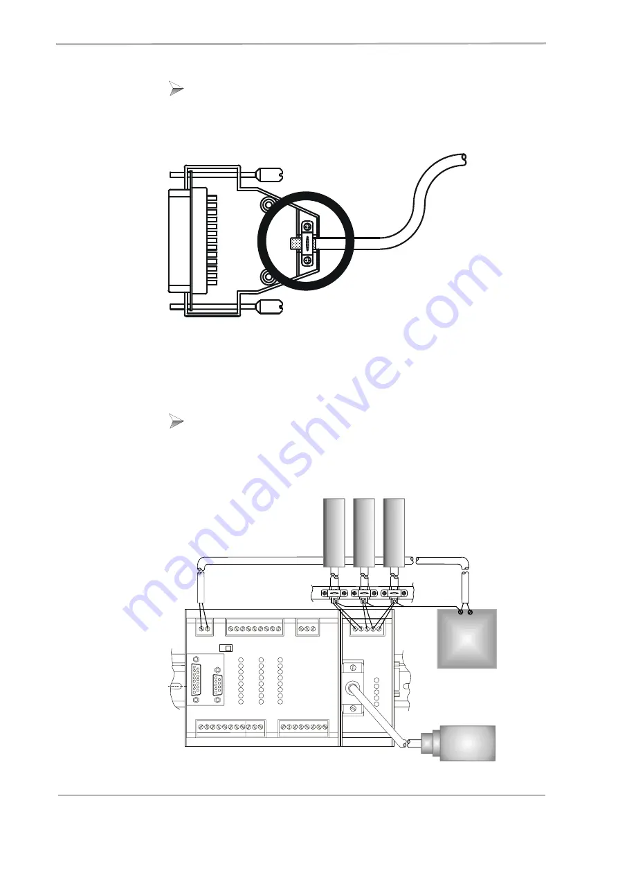
Fig. 1: Shielding of SUB-D connectors in conformity with EMC standards.

Fig. 2: Shielding of screw terminals in conformity with the EMC standards.

Only use metallized connectors, e.g. SUB-D with metallized housing. 
Make sure that the strain relief is directly connected with the housing here 
as well (see Fig. 1).

If the shield cannot be attached to the connector, for example, with a screw 
type terminal: 

It is important that shield and strain relief are highly conductive and directly 
connected to a grounded surface with the greatest possible surface area. 
When doing so, grounding must be implemented in a way that the 
unshielded portion of the cable is as short as possible (refer to Fig. 2).

-   +

Trans-
former

DC 24 V

JX2-CNT1

Jetter

REF

K1

K2

K0

S

S 0V

STR

0V

REF

INPUT

X21

X61

ENCODER

Incremental

encoder

0V 24V

1

2

3

4

5

POWER

INPUT

Nano-B

Jetter

OUTPUT

SM

COUNTER

IN  ANALOG  OUT

6

7

8

A

B

0V

0V

1

2

3

4

0V OUT 0V

24V

1

2

3

4

5

6

7

8

DIR ST

0V

STOP

RUN

IN

OUT

24V

5V

RUN

ERR

DIR

STEP

A

B

1

2

3

4

5

6

7

7

1

2

3

4

5

6

7

8

R

e

ference sw

itch

Strobe s

e

ns

or

Coun

ter

Содержание JetWeb JX2-CNT1

Страница 1: ...Item 608 633 15 Revision 3 02 4 June 2010 Printed in Germany JetWeb JX2 CNT1 Peripheral Module User Manual ...

Страница 2: ...l not necessarily be documented in every single case This manual and the information contained herein have been compiled with due diligence However Jetter AG assume no liability for printing or other errors or damages arising from such errors The brand names and product names used in this document are trademarks or registered trademarks of the respective title owner ...

Страница 3: ...e Technical Hotline 49 7141 2550 444 Telefax 49 7141 2550 425 E Mail Sales sales jetter de E Mail Technical Hotline hotline jetter de Internet address http www jetter de This User Manual is an Integral Part of the JetWeb Module JX2 CNT1 To be entered by the customer Copyright 2010 by Jetter AG All rights reserved Type Serial Year of manufacture Order Inventory Place of operation ...

Страница 4: ...ibutions on your part and would ask you to contact us This will help us to produce manuals that are more user friendly and to address your wishes and requirements This manual contains important information on how to transport erect install operate maintain and repair the JX2 CNT1 module Therefore the persons carrying out these jobs must carefully read understand and observe this manual and especia...

Страница 5: ... sign indicates hazard of life due to electric shock caused by a high operating voltage Warning This sign is to indicate hazard of serious physical damage or death due to accidentally touching dangerous parts of the device Warning You have to wear goggles Failure to comply may lead to bodily injuries Important This sign is to indicate a possible impending situation which might bring damage to the ...

Страница 6: ...sary efforts Enumerations are marked by full stops strokes or scores Operating instructions are marked by this arrow Automatically running processes or results to be achieved are marked by this arrow Reference to PC keyboard and HMI keys Reference to a program or file This symbol informs you of additional references data sheets literature etc associated with the given subject product etc It also h...

Страница 7: ...3 Instructions on EMI 15 2 Introduction 19 2 1 Product Description 19 2 2 Ordering Information 19 2 3 Update information 21 2 4 System Requirements 21 3 Physical Dimensions 23 4 Operating Conditions 25 5 Technical Data 29 6 Installation Guide 35 6 1 Installation Steps 35 6 2 Notes on Safety as regards the Installation 36 6 3 Notes on Safety as regards Commissioning 37 6 4 General Information 38 6 ...

Страница 8: ...l Counter 63 10 Dual Channel Counter 65 10 1 Reversal of Counting Direction 65 10 2 Count Value 65 10 3 Dual Channel Counter as Single Channel Counter 66 10 4 Referencing 68 10 4 1 Setting the reference position 68 10 4 2 Setting the Reference Offset 69 10 5 Reference Offset 70 10 6 Digital Filter 71 10 7 Strobe Function 72 11 SSI Absolute Encoder 73 11 1 Reading in SSI data 73 11 1 1 Standard For...

Страница 9: ...JX2 CNT1 Table of Contents Jetter AG 9 12 1 Sample Program 84 13 Master Slave Operation 87 13 1 Mode 1 Operation along with JX2 SV1 etc 88 13 2 Mode 2 Operation along with JM 2xx 91 ...

Страница 10: ...Table of Contents JetWeb 10 Jetter AG ...

Страница 11: ...ngle channel counter is for counting events The module JX2 CNT1 is supplied with power from the Jetter system bus that is by the basic unit the controller in the case of centralized arrangement In the case of remote arrangement by the power supply module JX2 PS1 The supply voltage of the JX2 CNT1 module is DC 5 V This operating voltage is classified as SELV Safety Extra Low Voltage The JX2 CNT1 mo...

Страница 12: ...fore not released by Jetter AG The installation of such parts may impair the safety and the proper functioning of the JX2 CNT1 module Any liability on the part of Jetter AG for any damages resulting from the use of non original parts and equipment is excluded 1 1 5 Repairing and Servicing the JX2 CNT1 Module The JX2 CNT1 module must not be repaired by the operator itself The JX2 CNT1 module does n...

Страница 13: ...tructions Jetter AG 13 1 1 6 Decommissioning and Disposal of the JX2 CNT1 Module Decommissioning and disposal of the JX2 CNT1 module are subject to the environmental legislation of the respective country in effect for the operator s premises ...

Страница 14: ...ier and cover of the terminal box must never be shunted or by passed Dismantled protective equipment must be reattached prior to commissioning and checked for proper functioning Malfunctions or other damages are to be reported to a responsible person at once Safeguard the JX2 CNT1 module against misuse or accidental use Only qualified experts are allowed to carry out repairs Markings information s...

Страница 15: ...ote 016 On principle physical separation should be maintained between signal and power lines We recommend spacings greater than 20 cm Cables and lines should cross each other at an angle of 90 Shielded cables must be used for the following lines Analog lines data lines motor cables coming from inverter drives servo output stage frequency converter lines between components and interference suppress...

Страница 16: ...portant that shield and strain relief are highly conductive and directly connected to a grounded surface with the greatest possible surface area When doing so grounding must be implemented in a way that the unshielded portion of the cable is as short as possible refer to Fig 2 Trans former DC 24 V JX2 CNT1 Jetter REF K1 K2 K0 S S 0V STR 0V REF INPUT X21 X61 ENCODER Incremental encoder 0V 24V 1 2 3...

Страница 17: ...ns the following must be ensured The shielding must be clamped under a strain relief with the greatest possible surface area The connection between shielding and ground must be electrically conducting The length of unshielded conductor ends must not exceed 8 cm refer to Fig 2 ...

Страница 18: ...1 Safety Instructions JetWeb 18 Jetter AG ...

Страница 19: ...y Jetter AG The single channel counter is used e g as workpiece counter 2 2 Ordering Information Jetter system bus connecting cable Designation Description Article No JX2 CNT1 Counter module 1 dual channel counter 1 MHz 1 single channel counter 10 kHz or 1 SSI absolute encoder 1 single channel counter 10000139 Jettersystem bus cable Cable assy 530 length 0 2 m 0 5 m 1 0 m 1 5 m 3 m 4 m 5 m other l...

Страница 20: ... system of JX2 CNT1 modules from JetSym The operating system can be updated only by Jetter AG 2 4 System Requirements Software Versions Module Minimum Software Version JX2 CNT1 3 02 Controller Minimum Software Version JC 241 JC 243 JC 246 3 00 NANO B NANO C NANO D 2 01 JX6 SB I for JC 647 MC DELTA JC 800 2 12 ...

Страница 21: ...JX2 CNT1 3 Physical Dimensions Jetter AG 21 3 Physical Dimensions Fig 3 Front View JX2 CNT1 Fig 4 Side View JX2 CNT1 ...

Страница 22: ...connector SUB D 9 pins Encoder connection Female connector SUB D 15 pins Counter Connection COMBICON terminal block Dimensions H x W x D in mm 115 x 45 x 68 Housing bottom Aluminium powder coated Color blue Housing cover Steel sheet metal coated with AlZn Weight 190 g Installation DIN rail EN 50022 35 x 7 5 ...

Страница 23: ...conductive contaminants Max Operating Altitude max 2 000 m above sea level DIN EN 61131 2 Operating Parameters Mechanical Data Parameter Value Reference Free Falls Withstanding Test Height of fall units within packing 1 m DIN EN 61131 2 DIN EN 60068 2 32 Vibration resistance 10 Hz 57 Hz with an amplitude of 0 0375 mm for continuous operation peak amplitude of 0 075 mm 57 Hz 150 Hz 0 5 g constant a...

Страница 24: ...µV m at 10 m distance class B DIN EN 50081 1 DIN EN 55011 DIN EN 50081 2 Operating Parameters EMC Enclosure Parameter Value Reference Magnetic field with mains frequency 50 Hz 60 Hz 30 A m DIN EN 61000 6 2 DIN EN 61000 4 8 RF field amplitude modulated Frequency band 27 1 000 MHz Test field strength 10 V m AM 80 at 1 kHz Criterion A DIN EN 61131 2 DIN EN 61000 6 2 DIN EN 61000 4 3 ESD Discharge thr...

Страница 25: ...ion A DIN EN 61131 2 DIN EN 61000 6 2 DIN EN 61000 4 4 Operating Parameters EMC Signal Ports Operating Parameters EMC Immunity to Interference of DC Power Supply I Os Parameter Value Reference Asymmetric RF amplitude modulated Frequency band 0 15 80 MHz Test voltage 10 V AM 80 at 1 kHz Source impedance 150 Ohm Criterion A DIN EN 61000 6 2 DIN EN 61000 6 2 Burst fast transients Test voltage 2 kV tr...

Страница 26: ...JetWeb 26 Jetter AG ...

Страница 27: ... coated with AlZn Installation DIN rail EN 50022 35 x 7 5 Logic Circuit Power Supply Power supply DC 5 V supplied by system bus Centralized arrangement via basic unit remote arrangement via power supply module JX2 PS1 Current consumption from system bus 200 mA max module logic circuit and sensor supply Power dissipation of logic circuit 0 5 W Connection to System Bus Connection to the basic unit v...

Страница 28: ... Single channel counter 24 V signal level 1 SSI absolute encoder Counters which can be operated simultaneously Single channel and dual channel counter or Single channel counter and SSI encoder Single Channel Counter 24 V Type of connection Terminal block X21 Maximum counting rate minimum pulse width 10 kHz 50 µs Signal Level 24 V Operating Point Low level up to 2 V High level 20 V 30 V Input curre...

Страница 29: ...nce switch X21 REF Strobe signal X21 STR DC 24 V relating to X21 0V at max 6 mA each Operating points Low level up to 2 V High level 20 V 30 V Dual Channel Counter 5 V Maximum counting rate 1 MHz Signal level 5 V differential voltage symmetrical antivalent to RS 422 do not use terminating resistors Terminating resistor Not installed Electrical isolation None Counting method Quadruple evaluation Se...

Страница 30: ...d Single evaluation Selection of counting direction Yes via hardware based on signal K2 SSI Encoder Type of connection Female connector SUB D 15 pins X61 Power supply for encoders with operating voltage of DC 5 V DC 5 V 5 100 mA max short circuit proof via X61 Position resolution 10 24 bits Type of signal decoding Gray code and binary code Accepted data formats Standard format Left justified Right...

Страница 31: ...expansion modules such as JX SIO and JX2 in your electric cabinet Mount the module and any expansion modules to the DIN rail as described in the corresponding user manuals Connect the module to the corresponding controller such as JC 24x NANO A B C D etc using a system bus cable Connect any further expansion modules using the correct cable Launch JetSym and set the communication parameters Switch ...

Страница 32: ...unplug plug in connectors while they are energized Also do not unscrew screwed connections of energized components Failure to comply with these rules may cause voltage peaks and thus electromagnetic interferences which may result in damages to the equipment as well as in electrical hazards to persons Therefore switch off the operating voltage of the machine before carrying out any work on it Befor...

Страница 33: ...l only Prior to commissioning please do the following Reattach dismantled protective equipment and check it for proper functioning This way protection from moving parts of the machine will be achieved Connect only devices or electrical components to the signal lines of the JX2 CNT1 module that have been sufficiently isolated from the connected electric circuits Protect the JX2 CNT1 module and the ...

Страница 34: ...he 0 V signal is connected to chassis ground Trans former DC 24 V JX2 CNT1 Jetter REF K1 K2 K0 S S 0V STR 0V REF INPUT X21 X61 ENCODER Incremental encoder 0V 24V 1 2 3 4 5 POWER INPUT Nano B Jetter OUTPUT SM COUNTER IN ANALOG OUT 6 7 8 A B 0V 0V 1 2 3 4 0V OUT 0V 24V 1 2 3 4 5 6 7 8 DIR ST 0V STOP RUN IN OUT 24V 5V RUN ERR DIR STEP A B 1 2 3 4 5 6 7 7 1 2 3 4 5 6 7 8 Reference switch Strobe sensor...

Страница 35: ...al area 0 25 2 5 mm2 Torque for input plug screws 0 5 0 6 Nm The maximum stripping length for input lines is 7 mm The accepted VDE guidelines must be followed Bladed screw driver 0 6 x 3 5 x 100 mm Connecting Cable Specifications Not needed Cable Shielding Make sure that the signal lines are shielded see Fig 6 Clamp the shield with the greatest possible surface area under the grounding clamp and e...

Страница 36: ...of LEDs Terminal Block X21 Single Channel Counter Pin Signal Comment X21 S X21 0V Counting signal 0 V Counter input DC 24 V max 6 mA Low level up to 2 V High level 20 V 30 V Reference potential Signal LED Single Channel Counter LED Color State Function S amber Off Low level of counter input is lit High level of counter input ...

Страница 37: ...order to use the strobe function a sensor can be connected to terminal block X21 STR 6 7 1 Description of Connections Encoder Signals 15 Pin Female SUB D Connector X61 Dual Channel Counter 5 V Differential Voltage View Pin Signal Comment 1 2 3 4 5 6 7 8 9 10 11 12 13 14 15 GND K0 K0 K1 K1 K2 K2 Do not connect Do not connect DC 5 V 5 Do not connect Do not connect Do not connect Do not connect Do no...

Страница 38: ...ded View Pin Signal Comment 1 2 3 4 5 6 7 8 9 10 11 12 13 14 15 GND K0 Do not connect K1 Do not connect K2 Do not connect Do not connect Do not connect Do not connect Do not connect Do not connect Do not connect Do not connect Do not connect Reference potential Channel N zero pulse Channel A Channel B 1 8 9 15 ...

Страница 39: ...prox 20 m Other specifications see specifications of cables on encoder side Cable Shielding Connect the shield with the greatest possible surface area to the metallized housing 15 Pin Female SUB D Connector X61 Dual Channel Counter as 24 V Single Channel Counter View Pin Signal Comment 1 2 3 4 5 6 7 8 9 10 11 12 13 14 15 GND K0 Do not connect K1 Do not connect K2 Do not connect Do not connect Do n...

Страница 40: ... Cable Not needed Cable Shielding Make sure that the signal lines are shielded see Fig 6 Clamp the shield with the greatest possible surface area under the grounding clamp and establish an electroconductive connection with the grounding block Fig 10 Connection of strobe sensor and reference switch to X21 Terminal Block X21 Strobe and Reference Switch Input Pin Signal Comment X21 STR X21 REF X21 0V...

Страница 41: ... inverted high level applied to channel A is lit High level applied to channel A inverted low level applied to channel A K2 amber Off Low level applied to channel B inverted high level applied to channel B is lit High level applied to channel B inverted low level applied to channel B K0 amber Off Low level applied to channel N zero pulse inverted high level applied to channel N is lit High level a...

Страница 42: ... data line Inverted clockline Clockline Power supply for encoders with operating voltage DC 5 V short circuit proof up to 100 mA JX2 CNT1 Jetter REF K1 K2 K0 S S 0V STR 0V REF INPUT X21 X61 ENCODER X 1 8 9 15 Important Reversal of CLOCK signals produces invalid position values If DATA and DATA are reversed the JX2 CNT1 module reads out the first complement of the binary or Gray coded encoder value...

Страница 43: ...etallized housing Important Binary Coding If DATA and DATA are correctly connected to the encoder the JX2 CNT1 indicates that the counting direction is reversed compared to the counting direction of the encoder In order to maintain the original counting direction in JX2 CNT1 the counting direction must be reversed by means of bit 9 in register 3xx3 Status Controller Clock frequency Length 100 kHz ...

Страница 44: ...d via SUB D connector These connectors excel by their reliable mechanical and electrical connections as well as good EMI characteristics Important A detailed description of this topic is given in the User Manual of the controller Refer to this manual for further information on the system bus such as cable lengths baud rate monitoring functions etc Centralized and Remote Arrangement of Expansion Mo...

Страница 45: ...lligent expansion modules For a remote module set consisting of a mix of intelligent and non intelligent expansion modules a JX2 PS1 is required since intelligent modules are not able to supply non intelligent modules with current and voltage The remote modules are controlled by the application program as if they were directly connected to the controller 0 V 1 2 3 4 INPUT INPUT 5 6 7 8 0 V 1 5 2 6...

Страница 46: ...connecting 0 25 0 60 mm2 Female connector BUS IN side JX2 PS1 9 pin female SUB D connector in metallized housing quality grade 3 Diameter of the cable apt for connecting 0 25 0 60 mm2 JetControl 24x and modules JX2 PS1 and modules JX2 PS1 and modules JX2 PS1 and modules JX2 PS1 and modules System bus System bus System bus System bus JetWeb Jetter JC 246 1 3 5 7 2 4 6 8 INPUT 9 11 13 15 10 12 14 16...

Страница 47: ...um 60 km 250 kBaud maximum 60 km 125 kBaud maximum 60 km Number of cores 5 Shield Complete shielding no paired shielding Twisting Core pairs CL and CH must be twisted Ω Ω Ω Ω Allowed Cable Lengths Baud Rate Max cable length Max tap line length Max overall tap line length 1 MBaud 30 m 0 3 m 3 m 500 kBaud 100 m 1 m 39 m 250 kBaud 200 m 3 m 78 m 125 kBaud 200 m Note The maximum cable length depends o...

Страница 48: ...19 Note On the BUS OUT side of the system bus cable pins 3 and 5 have to be bridged For more information refer to the table below System Bus Cable Cable Confection 530 Shield BUS OUT Connect shield with the greatest possible surface area Use metallized housing only BUS IN Pin Signal Pin 1 CMODE0 1 2 CL 2 3 GND 3 4 CMODE1 4 5 TERM not connected 5 6 Unassigned 6 7 CH 7 8 Unassigned 8 9 Do not connec...

Страница 49: ...reset to parameterize the JX2 CNT1 apart from registers 8 virtual outputs are available Appendix A provides a brief overview of these virtual outputs see Appendix A Overview Outputs page 97 7 1 1 Addressing the Virtual Outputs The address is derived from the module position and the number of the corresponding output Addressing in the case of JC 24x NANO A B C D controllers Output number xxzz Meani...

Страница 50: ... x x 1 m z z I O number 01 08 I O module number 02 32 Submodule socket 1 2 4 Output number 53CM xxzz x x z z I O number 01 08 Module number JX2 I O 02 32 System bus module 1 2 Module board number 1 3 2 Input 3 Output Area 5 M 2 3 C 5 Note To determine the module number the digital input or output modules are counted Intelligent modules such as JX2 SV1 JX2 SM2 JX2 PID1 modules etc located among the...

Страница 51: ...16 1 JX2 SV1 and 1 JX2 CNT1 Basic controller JC 24x I O Module JX2 IO16 I O Module JX2 IO16 Input module JX2 CNT1 Module 1 Module 2 Module 3 Module 4 Input 101 116 Outputs 101 108 Input 201 208 Output 201 208 Input 301 308 Output 301 308 Output 401 408 Module Basic controller JC 24x Output module JX2 IO16 Servo module JX2 SV1 Input module JX2 CNT1 Non intelligent Module 1 Module 2 Module 3 Intelli...

Страница 52: ...sing The register address is derived from the module number and the respective register number Addressing register numbers in the case of JC 24x NANO B C D controllers The register address always starts with the area number 3 Register number 3xxz Meaning For more information refer to the manual on the corresponding controller Note Outside this chapter of this manual register numbers are specified ...

Страница 53: ...ontroller I O module number 1 is allocated to the controller or the system bus module JX6 SB I Starting from there I O module numbers are counted left to right That is module number 2 is assigned to the first I O module that follows the controller or the system bus module 3 m 0 3 x x z Register number 0 9 I O module number 2 0 30 JX2 I O module area 03 Submodule socket 1 3 Area 3 C M 0 3 x x z Reg...

Страница 54: ...ing applies to these digits Register number 3000 I O module number 2 10 local register number Example 3 Determining Register Numbers Determinig the register number of the third I O expansion module connected to a JetControl 246 I O module number 4 Local register number 9 Register number 3000 4 2 10 9 3029 ...

Страница 55: ...e following reset 0b 00000000 00000000 Note On write access bits 0 4 and 6 are automatically reset irrespective of whether the bits of the value to be entered are already set or not Meaning of the individual bits Bit 0 Dual channel counter Strobe status Indicates whether the count value has been strobed by the dual channel counter This value is reset on write access to register 3xx3 0 No strobe 1 ...

Страница 56: ...eous change of tracks K1 and K2 or too high a counting frequency or rate has been detected The latter applies only with the input filter enabled see register 3xx8 Filter frequency This value is reset on write access to register 3xx3 0 No Z track error 1 Z track error Value following reset 0 Bit 7 Reserved Meaning of the individual bits Bit 8 Reserved Bit 9 SSI Reversal of counting direction Select...

Страница 57: ... 3xx7 The time base for frequency measurement is displayed in register 3xx1 Value following reset 0 Bit 13 Reserved Bit 14 Master mode Selection Is for selecting the master mode which is used to output the counter value in register 3xx0 on the system bus 0 Mode 1 Operation along with JX2 SV1 or CAN DIMA 1 Mode 2 Operation in synchronous mode JetMove 2xx JetMove D203 JetMove 105 Bit 15 Reserved Reg...

Страница 58: ...8 2 Firmware Version JetWeb 58 Jetter AG ...

Страница 59: ...le channel counter can be seen from register 3xx4 Single channel counter count value The count value is incremented or decremented whenever the edge of the counting signal rises It is not possible to change this setting The count value can be changed by manually entering a value into register 3xx4 Note The counting direction is set via virtual output xx05 of the JX2 CNT1 module Register 3xx4 Singl...

Страница 60: ...JetWeb 60 Jetter AG ...

Страница 61: ...he dual channel counter can be zeroed by means of a reference switch and the K0 signal of an incremental encoder The strobe function is used to save the count value at the time when the strobe signal was issued capture function The built in digital filter is for filtering out interfering frequencies out of the useful signal The digital filter is disabled by default 10 1 Reversal of Counting Direct...

Страница 62: ...count value is incremented or decremented at every positive edge of the counting channel K1 The count value of the single channel counter can be seen from register 3xx0 Count value or it can be changed there manually R3xx0 count internal count R3xx1 reference position offset Note By writing a value into register 3xx0 exact referencing of the position value from the incremental encoder cannot be ac...

Страница 63: ...JX2 CNT1 10 Dual Channel Counter Jetter AG 63 Fig 13 Signal waveform for single channel counting ...

Страница 64: ...cing this output is to be set by the user STR disabled REF enabled If this output has already been set for example due to a previous referencing it must be reset first The referencing function sets the count value in register 3xx0 to zero if the following condition is fulfilled R3xx0 count value 0 if K0 zero pulse of the incremental encoder 1 AND REF reference switch 0 Please also refer to Fig 14 ...

Страница 65: ...is zeroed using the reference function This way the reference position is set to position 0 refer to Setting the Reference Position on page 64 Register 3xx1 Dual channel counter Offset can be used to define any position as reference position refer to Reference Offset on page 66 In this connection the previously determined reference position of the mechanical system is maintained ...

Страница 66: ...using the reference function register 3xx0 0 Via offset register 3xx1 the reference position is to be set to 10 000 increments The user enters 10 000 into register 3xx1 The count value is set to 10 000 increments or to a value around 10 000 if the incremental encoder has moved during this process or is between 2 PPR counts and is permanently oscillating Status bit 12 0 Register 3xx1 Dual channel c...

Страница 67: ... are taken into account and all signals the fundamental frequency are filtered out and ignored by the counter The fundamental frequency is not directly entered into register 3xx8 Rather a value is entered which corresponds to a fundamental frequency The value corresponding to the desired fundamental frequency is calculated by the following formula Register 3xx8 Dual channel counter filtering frequ...

Страница 68: ...gnal activation of the JX2 CNT1 module is reset 0 STR enabled REF disabled If this is the case the count value is stored every time the edge of the strobe signal rises Bit 0 Dual channel counter strobe status in register 3xx3 Status Controller shows whether a strobe signal has been issued and the count value in register 3xx2 is valid If bit 0 equals to 1 a strobe event has occurred and the stored ...

Страница 69: ...ation on the SSI interface refer to Technical Data in chapter 5 Technical Data page 27 For information on installation refer to chapter 6 8 SSI Encoder page 42 11 1 Reading in SSI data The following subchapters first introduce the data formats prevailing in the market Then this manual explains which data formats can be read by the JX2 CNT1 and how they are read in The position value which has been...

Страница 70: ...des the resolution into number of revolutions to the left of the center line and steps per revolution to the right of the center line If less than 12 bits are needed for the number of revolutions unused places are filled with leading zeroes up to the required length of 12 bits On the other hand if less than 12 bits are needed for the number of steps per revolution unused places are filled with tra...

Страница 71: ...f fir tree format However the position bits can be placed at any location within the maximum clock number Leading or trailing zero bits required to reach the maximum clock number are inserted around the position bits Here special bits or a parity bit can be added as well They can be placed directly after the position bits or after the trailing zero bits Fig 17 SSI Left or right justified data form...

Страница 72: ...mples apply to both types of signal coding Gray and binary coding Example 1 In this example 10 position bits in usual standard format are read As number of clocks the value 10 must be entered The encoder does not transmit a parity bit therefore parity check must be disabled Position range displayed in register 3xx0 0 1023 in steps of 1 Example 2 Like example 1 but with one additional clock as the ...

Страница 73: ...n read out at 25 clocks and only the lowest 24 bits can be taken over the highest bit which has been read out in clock 1 gets lost Position range displayed in register 3xx0 8 388 608 8 388 607 in steps of 32 768 However it is also possible to reduce the number of clocks and to do without reading out the trailing zero bits Thus the position values remains at the correkt binary location Example 9 Li...

Страница 74: ...11 1 Reading in SSI data JetWeb 74 Jetter AG Fig 18 Examples Reading in Different SSI Formats ...

Страница 75: ...rmat of the related SSI encoder For more information refer to Reading in SSI data on page 69 The clock frequency depends on the length of the encoder cable For more information refer to chapter 6 8 SSI Encoder page 42 The value of register 3xx6 number of clocks and clock rate is calculated by the formulas given in the following table In this table configuration values for clock rates of 100 kHz an...

Страница 76: ...onfiguration Values Number of Clocks 100 kHz 200 kHz 10 1 543 21 503 11 23 591 23 551 12 25 639 25 599 13 27 687 27 647 14 29 735 29 695 15 31 783 31 743 16 33 831 33 791 17 35 879 35 839 18 37 927 37 887 19 39 975 39 935 20 42 023 41 983 21 44 071 44 031 22 46 119 46 079 23 48 167 48 127 24 50 215 50 175 25 52 263 52 223 A number of clocks 1 x 2 1 x 1024 B 16 000 000 clock rate x 2 41 Register 3x...

Страница 77: ...information on how to set the correct number of clocks refer to Reading in SSI data on page 69 If the SSI encoder provides a parity bit in the data stream this bit must be taken into account when specifying the number of clocks in register 3xx6 SSI configuration That is if for example the encoder provides 24 position bits and one parity bit the number of clocks must be set to 25 bits If the SSI en...

Страница 78: ... only be used with SSI encoders which meet the following requirements 24 bit position resolution no special bits or parity bits in the data stream Status bit 12 0 Register 3xx7 Counter of SSI parity errors Function Description Read Actual number of parity errors Write Start value of parity error count Value range 8 388 608 8 388 607 Value following reset 0 Note If the counting direction is reverse...

Страница 79: ... time base is set in register 3xx1 Frequency Time base Both registers have got a double function Register 3xx7 is used to read or write the SSI parity error counter and register 3xx1 is used to read or write the dual channel offset The function of these two registers is set by means of bit 12 in register 3xx3 Status Controller The frequency value is calculated as follows Count value n is captured ...

Страница 80: ... JetSym Symbol Listing JetSym Program Listing Status bit 12 1 Register 3xx1 Frequency Time Base Function Description Read Present time interval of frequency measurement Write New time interval Value range 1 255 10 ms Value following reset 10 100 ms Registers rmStatusControl 3003 Status Controller rmFrequency 3007 Frequency value rmTimeBase 3001 Frequency time base rRPM 100 Speed in RPM Bit Symbols...

Страница 81: ...time base nRPM INT AT VL 100 Speed in RPM Register bits bnSelectFrequency BOOL AT VL 3003 12 Bit for selecting the frequency display END_VAR Program Frequency Measurement Initialization bnSelectFrequency TRUE nmTimeBase 100 Time interval to 1 s bnSelectFrequency FALSE Speed calculation is executed at regular intervals bnSelectFrequency TRUE nRPM nmFrequency 60 4096 bnSelectFrequency FALSE ...

Страница 82: ...12 1 Sample Program JetWeb 80 Jetter AG ...

Страница 83: ...he count value of the dual channel counter or SSI encoder can be transmitted as master axis position for master slave operation to one or more Jetter axis modules via system bus Important If JX2 CNT1 is operated in master slave operation and one or more slave axes are coupled in changes relating to the count value made by the user may have negative effects on the slave axes For example entering a ...

Страница 84: ... master slave operation in mode 1 and on the configuration of the axis module or drive control module for operation along with JX2 CNT1 refer to the following manual can dima_user s_manual_editon_1_0 pdf chapter Functioning Principle of the Follower Function Plan Configuration The function plan below shows the registers which are required for configuring the JX2 CNT1 as master axis in mode 1 as we...

Страница 85: ...3xx5 Transmission Rate Actual Position Status bit 14 0 Register 3xx5 Transmission Rate Actual Position Function Description Read Present transmission rate for Actual Position Write New transmission rate Value range 0 5 ms 0 approx 250 µs Value following reset 0 approx 250 µs Sample Program A JX2 CNT1module which is located at the first I O position after the basic device is to be used as master ax...

Страница 86: ...Rate INT AT VL 3005 Transmission rate Register Bits bnSelectMS_Modus2 BOOL AT VL 3003 14 Bit for selecting master slave operation Outputs boSendMasterPos BOOL AT QX 203 Virtual output xx03 END_VAR Program Initializing Master Slave Operation in Mode 1 bnSelectMS_Modus2 FALSE if set nmSendRate 1 Transmission rate 1 ms boSendMasterPos TRUE ...

Страница 87: ...ak this rule If you require an additional master axis for another technology group you must use a JM 2xx as second master axis Further Information For detailed information on configuration and operation of master slave systems based on JM 2xx modules refer to the following manual jm2xx_at_jetcontrol_bi_xxxx_user_information pdf chapter Technology Functions Function Plan Configuration The function ...

Страница 88: ...s number Write New master axis number Value range 0 1 2 In the case of 0 sending is disabled even if virtual output xx03 is set Value following reset 0 SampleProgram A JX2 CNT1module which is located at the first I O position after the basic device is to be used as master axis with master axis number 1 Registers rmStatusControl 3003 Status Controller rmMasternumber 3005 Master number Bit Symbols n...

Страница 89: ...r Register bits bnSelectMS_Modus2 BOOL AT VL 3003 14 Bit for selecting master slave operation Outputs boSendMasterPos BOOL AT QX 203 Virtual output xx03 END_VAR Program Initializing Master Slave Operation in Mode 2 bnSelectMS_Modus2 TRUE nmMasternumber 1 Master number 1 boSendMasterPos TRUE ...

Страница 90: ...13 2 Mode 2 Operation along with JM 2xx JetWeb 94 Jetter AG ...

Страница 91: ...JX2 CNT1 Appendices Jetter AG 95 Appendix ...

Страница 92: ...Appendices JetWeb 96 Jetter AG ...

Страница 93: ...r position on the system bus enabled xx04 Encoder Selection 1 Dual channel counter enabled 2 Page 75 Page 61 0 dual channel counter enabled 1 SSI encoder enabled Dual Channel Counter xx01 Signal Activation 1 STR enabled REF disabled 2 Page 64 0 STR enabled REF disabled 1 STR disabled REF enabled STR strobe function REF reference function When this bit is set to 1 bit 3 in register 3xx3 Status Cont...

Страница 94: ...Appendices JetWeb 98 Jetter AG xx08 Parity Settings 1 odd parity 2 Page 75 0 odd parity 1 even parity Output Number Name 1 Default value 2 Cross reference ...

Страница 95: ...JX2 CNT1 Appendices Jetter AG 99 ...

Страница 96: ...resolution 2 0 3 Page 69 3xx1 Status bit 12 0 Dual channel counter offset R W 1 8 388 608 8 388 607 2 0 3 Page 66 3xx1 Status bit 12 1 Frequency time base R W 1 1 255 2 10 3 Page 78 3xx2 Dual channel counter strobe value R 1 8 388 608 8 388 607 2 0 3 Page 68 3xx3 Status Controller R W 1 bit oriented 16 bits 2 0b 00000000 00000000 3 Page 55 Status Bits Bit 0 Dual channel counter Strobe status 0 1 n...

Страница 97: ...x7 SSI Parity error counter R3xx1 Frequency display R3xx7 Frequency time base Bit 13 Reserved Bit 14 Master mode selection 0 1 Operation along with JX2 SV1 CAN DIMA Operation in synchronous mode JetMoves Bit 15 Reserved 3xx4 Single channel counter count value R W 1 8 388 608 8 388 607 2 0 3 Page 59 3xx5 Status bit 14 0 Transmission rate actual position R W 1 0 5 2 0 3 Page 89 3xx5 Status bit 14 1 ...

Страница 98: ...7 2 0 3 Page 78 3xx7 Status bit 12 1 Frequency display R 1 8 388 608 8 388 607 2 0 3 Page 77 3xx8 Dual channel counter filtering frequency R W 1 0 32 704 2 0 3 Page 67 3xx9 Firmware version R 1 0 8 388 607 2 Firmware version 3 Page 57 Register Number Name R W 1 Value Range 2 Default value 3 Cross reference ...

Страница 99: ...JX2 CNT1 Appendices Jetter AG 103 ...

Страница 100: ...2 05 02 Sing Industrial Complex Singapore 569510 Singapore Jetter Schweiz AG Münchwilerstraße 19 CH 9554 Tägerschen Switzerland Jetter USA Inc 165 Ken Mar Industrial Parkway Broadview Heights OH 44147 2950 U S A Phone 65 6483 8200 Phone 41 719 1879 50 Telefon 1 440 8380860 Fax 65 6483 3881 Fax 41 719 1879 69 Fax 1 440 8380861 E Mail sales jetter com sg E Mail info jetterag ch E Mail bschulze jette...

Отзывы: