background image

29

TwinForce™ Series Waterblast Unit

11. 

Reduce the discharge flow by fully open

-

ing the bypass valve.

12.  With the engine at idle speed, disengage 

the clutch.

13.  The nozzles can now be installed on the 

discharge device(s). 

14.  Before waterblasting, adjust the lubrica-

tion line needle valves, if equipped. Refer 

to “Checking the Water Lubrication Sys

-

tem”, below.

Checking the Water Lubrication 

System

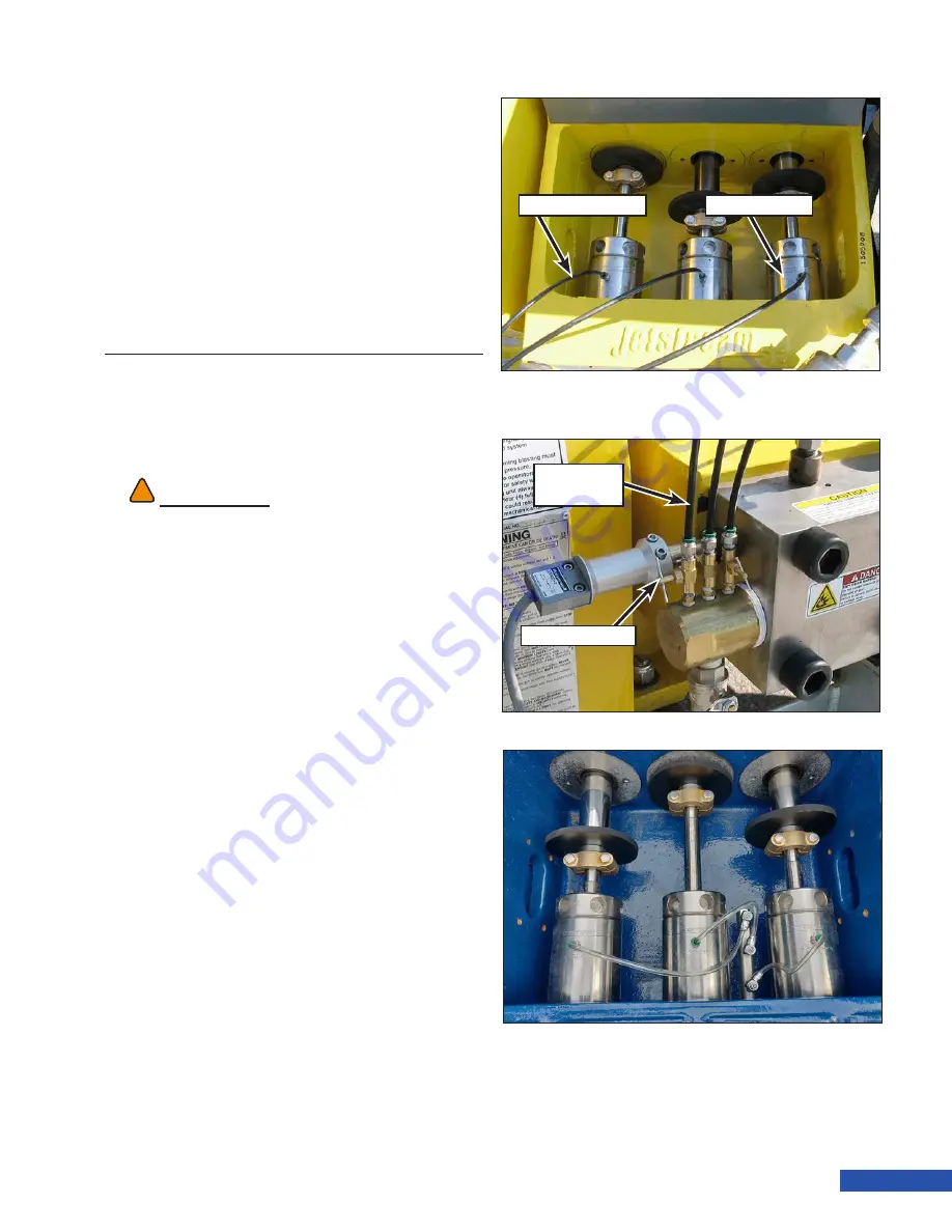
1.  Lift the rod box cover to view the water 

lubrication system.

2.  Look into the rod box and verify that lu-

brication water is flowing from the back 

of the gland nut at the plunger/gland nut 

intersection. The flow should be a small 

stream but should not splash onto the 

pony rods. (Figure 36).

3. 

Next, check the stuffing box temperature 

by very carefully placing your finger tips 

on the top of the stuffing box. The temper

-

ature should be cool to warm but still cool 

enough that you can keep your fingers on 

it for 10 seconds. 


If there is no water flow, or the tempera

-

ture is too hot, or if steam is visible, the 

needle valves need to be adjusted. 

4.  Adjust the needle valves (Figure 37) 

(needle valves are only included on pres-

sure fed setups. Gravity fed units will not 

utilize needle valves) to increase the 

water flow. Excessive splashing may 

occur, which could cause water to be 

drawn into the power end, contaminating 

the oil. Adjust the needle valves to pre-

vent excessive lubrication water flow. 

Re-check the lubrication water flow 

periodically during operation. 

WARNING

!

!

There are moving parts inside the rod box that can 

cause serious injury. Use extreme caution. Keep all 

tools out of the rod box while the pump is running.

Lubrication Line

Needle 

Valve

Lubrication Line

Stuffing Box

Figure 36:  Checking Lubrication.

Lubrication 

Line

Needle Valve

Figure 37:  Needle Valve Adjustment (40K).

Figure 38: 

5200 Series Water Lubrication System.

Содержание TwinForce Series

Страница 1: ...OPERATION MANUAL TwinForce Series Waterblast Unit...

Страница 2: ...Visual Safety System...

Страница 3: ...le or in part into another language Every reasonable effort has been made to ensure that the data given in this document is accurate however the information figures illustrations tables specifications...

Страница 4: ...bushings plungers nozzles rupture disks etc 4 Failures resulting from the machine being operated in a manner or for a purpose not recommended by Jetstream including failures or malfunctions resulting...

Страница 5: ...ssure 5 Use the Minimum Pressure Required 5 Be Prepared 5 Performing Maintenance or Repairs 5 Freezing Conditions 5 Store Components Properly 5 Long Term Storage 5 Trailer Safety 6 Tires and Rims 6 Av...

Страница 6: ...Activating the System 18 CONTROL PANEL 19 Jetstream Connections 20 Jetstream 3000 3600 4200Bareshaft Pump InstallationGuidelines 21 Models 21 Water Supply 21 Pulsation 21 Lubrication 22 Jetstream 520...

Страница 7: ...fe 43 PRESSURE CONVERSION 45 Converting a Pump 45 40K Hose Connections 52 SERVICE 53 Fluid End 53 Checking Manifold Bolt Torque 53 Rupture Disc Inspection 54 Packing Replacement 54 Uni Valve Service 6...

Страница 8: ...Crankshaft 88 TROUBLESHOOTING 93 TRAINING 95 Safety Training 95 New Start up Training 95 FS Solutions Training 95 Additional Training Opportunities 95 APPENDIX A TECHNICAL SPECIFICATIONS A 1 General U...

Страница 9: ...re not taken Warning is used to indicate the presence of a hazard which MAY cause serious physi cal injury or death and can result in serious property damange if proper precautions are not taken Cauti...

Страница 10: ...he following illustrations show common locations for safety decals Decals and their locations may vary for different units Always be familiar with the location and content of all safety decals on any...

Страница 11: ...3 TwinForce Series Waterblast Unit...

Страница 12: ...0 psi 1000 bar and lower pressures use at least four wraps of Teflon tape on male pipe NPT threads for sealing purposes Do not allow any tape to overlap the end of the fitting Tape fragments may enter...

Страница 13: ...om ponents with a lower pressure rating can be overlooked and explode if vigilance is not maintained Keep equipment pressure rating and warning tags intact Be Prepared If equipment malfunctions or a m...

Страница 14: ...ailer is equipped with electric brakes Before towing the trailer verify that the trailer brakes are working properly Breakaway System Jetstream trailers are equipped with break away brake systems to s...

Страница 15: ...UNx Pump The UNx pump uses the power from the engine to pressurize the source water into high pres sure output The pump is separated into two sections the power end and the fluid end The power end co...

Страница 16: ...o used to purge air during op eration start up Water Lubrication System The water lubrication system provides water to the packing in the pump The water lubri cates and cools for optimum operation of...

Страница 17: ...ump pressure by bleeding off excess water and diffusing it to low pressure Turning the knob allows the op erator to adjust pressure during operation and relieve pressure when not waterblasting The byp...

Страница 18: ...se to the manifold Control Panels Twin Force units come equipped with a total of 4 control panels The associated panels are ei ther marked with a 1 or a 2 Figure 12 Two control panels are able to cont...

Страница 19: ...14 is mounted on top of the pump for use when operating at 40K The filter is not connected during 15K or 20K operation A pressure gauge is mounted on the filter to monitor pressure in the filter A di...

Страница 20: ...to be filled separately for use with its as sociated engine The fuel tank caps are vented and lockable Keys are supplied with original shipment of the unit Batteries Two 12 volt lead acid batteries wi...

Страница 21: ...Figure 18 is attached to all fluid end manifolds The plate is stamped with the fluid end model number In addition the plate is stamped with plunger size and output pres sure related to that plunger s...

Страница 22: ...14 Operation Manual...

Страница 23: ...not being towed and can be used to level the unit Use the hand crank to adjust tongue height up or down The support capacity of the jack stands is 12 000 lb 5443 kg Adjustable Ball Hitch The adjustab...

Страница 24: ...le Optional Attach the grounding cable Figure 23 to the structure being cleaned to prevent sparks cre ated by static electricity Document Holder Optional A document holder Figure 23 is mounted in the...

Страница 25: ...the tow vehicle has its lights turned on Rear Lights and Reflectors The trailer is equipped with a row of rear mark ers lights Figure 25 required for trailers over 80 in 203 cm wide The lights will i...

Страница 26: ...oltage from the breakaway system battery is sent through the closed contacts in the switch to the brake magnets in the drum brakes The magnet actuates the brakes to stop the trailer The battery is con...

Страница 27: ...erride When switched to the ON position the override switch will ignore the low water level sensor and or the differential pressure switch secondary filter and the engine will run without water at the...

Страница 28: ...ns Each end of the tether cable connecting two panels for control of the same engine is iden tified as Near Side or Far Side Figure 29 This designates which panel that particular end should connect to...

Страница 29: ...et The 40K version requires 40 psi minimum supply pressure at full pump speed to operate All uid ends have a maximum inlet supply pressure of 75 psi The supply water should be clean and cold The maxim...

Страница 30: ...rod bushings are supplied oil via gravity from a collection trough above the crossheads The powerend has a level requirement to ensure oil lubricates the crank shaft tapered roller bearings and stays...

Страница 31: ...peed to operate As such it is supplied with lube water flow control valves mounted on a manifold in the rod box area All fluid ends have a maximum inlet supply pressure of 75 psi Rod Box The 5200 pump...

Страница 32: ...t rotates and pulls the crosshead backwards through the suc tion stroke the force between the connect ing rod journal bearing and the crankshaft decreases greatly This reduction in force and the rotat...

Страница 33: ...e to your Jetstream representative 5 Remove the pump wrench from the rod box Figure 31 CAUTION When mounting skid units on a trailer or truck orient the rain cap so the flapper on the exhaust stack op...

Страница 34: ...upply hose inside diameter must be large enough to supply 150 of the unit s maximum flow requirements The inside diameter of the high pressure discharge hose will be determined by the necessary length...

Страница 35: ...ition This allows the engine to start without a load from the pump 3 On 6000 series pump open the air side of the pulsation dampener and close it again to reset the diaphragm before operation 4 Move t...

Страница 36: ...ss valve clockwise just enough to obtain a generous flow of water through the discharge hose Allow the hose to flush for about 30 seconds Note A substantial amount of thrust may occur at the discharge...

Страница 37: ...box The temper ature should be cool to warm but still cool enough that you can keep your fingers on it for 10 seconds If there is no water flow or the tempera ture is too hot or if steam is visible t...

Страница 38: ...pressure ATTENTION If new packing was installed or if operating the pump for the first time the pump packing must be broken in properly Refer to Breaking In New Packing for instructions pump fluid en...

Страница 39: ...K molded packing It is not required for plastic packing New packing must be broken in to prevent damage and ensure optimal performance Break in should occur in three to four pressure increases over a...

Страница 40: ...e outer O rings Figure 42 on the valves have failed Note The larger O ring will leak to the rectangular weep hole Monitor the manifold for leakage during opera tion If leakage occurs immediately repla...

Страница 41: ...ssure If a bypass valve is on both fluid ends one should be completely closed 15K and 20K water travels through 20K hard pipe and hose Blue while 40K water travels through separately plumbed 40K hard...

Страница 42: ...34 Operation Manual...

Страница 43: ...Operation Only on page 42 and Filter Cartridge Replacement on page 43 for more in formation 50 Hours 1 Check Pump Drive Belt Tension Ensure the belts are properly tensioned per the tension decal under...

Страница 44: ...ould allow freezing in the pump or pip ing utilize the following procedure 1 Drain the water from the tank 2 Disconnect the water supply suction line and high pressure discharge hose from the manifold...

Страница 45: ...freeze has been discharged from the discharge port disengage the clutch and shut off the engine 12 Remove the funnel assembly from the suction port and reconnect the suction hose 13 Disconnect the wat...

Страница 46: ...RNING Tire installations that do not meet or exceed these specificationsmaycausetirefailureresultinginloss of trailer control and or bodily injury WARNING Failure to grease or properly seal wheel bear...

Страница 47: ...for the engagement of the brakes Recheck the battery voltage The voltage should be 1 or more volts low er than the previous measurement if the brakes are working If the brakes could not be heard or if...

Страница 48: ...40 Operation Manual...

Страница 49: ...this pump an expert that specializes in water quality must perform a water quality test If your water is found to exceed any of the allowable measurements in the chart below consult a specialist in wa...

Страница 50: ...approximately 7 to 10 psi 0 48 to 0 69 bar the pressure switch on the filter housing will trip and the engine will shut off to protect the unit from damage Replace the dirty filter cartridge if this o...

Страница 51: ...uge as more hours of operation are accumulated on the filter cartridge When the pressure on the filter gauge has dropped approximately 7 to 10 psi 0 48 to 0 69 bar with the unit operating at the same...

Страница 52: ...44 Operation Manual...

Страница 53: ...the following procedure to convert a pump to a different pressure 1 Relieve pressure from the pump shut off the engine and disengage the clutch 2 Turn off the water supply drain the water tank 3 Remov...

Страница 54: ...tall manifold mounting studs Figure 62 into the two open holes to allow for easier installation of the new manifold Note Manifold mounting studs can be purchased from Jetstream p n 54261 9 Continue re...

Страница 55: ...m each stuffing box 12 Remove the two bolts that secure each plunger coupling Figure 65 to the plung ers and remove the three couplings Note The coupling halves are matched and must be kept together C...

Страница 56: ...plunger coupling Figure 67 on each plunger and secure with the two bolts Tighten the bolts to 20 ft lb 27 N m 17 Ensure the gland nuts are tight Use the pump wrench and a 5 lb 2 kg hammer to tighten...

Страница 57: ...put the hinge rod in a substantial bind and it will be bent down slightly at the ends since it will be supporting the weight of the manifold block This centered position of the manifold will also ensu...

Страница 58: ...trunnions up or down until the manifold bolts thread in and out easily 22 Install the manifold bolts Figure 73 in the open holes and hand tighten 23 Remove the manifold mounting studs Figure 73 24 Ins...

Страница 59: ...Breaking in New Packing on page 31 ATTENTION If converting to a 40K fluid end the secondary filter must be plumbed for operation Refer to 40K Hose Connections When converting to 40K a charge pump is r...

Страница 60: ...let coupling When converting to 40K the front and rear pumps will be tied together Flow from the first pump will enter the manifold of the second pump and the combined flow will leave the second pump...

Страница 61: ...e of the gland nut holes 3 Use a 5 lb 2 kg hammer to hit the wrench in the direction Figure 82 to tighten the gland nuts Hit the wrench about three times using moderate force This will sup ply suffici...

Страница 62: ...off the water supply and drain the water tank 3 Open the rod box cover 4 Disconnect the water lubrication lines if equipped 5 Position the plunger to be serviced so that it is at bottom dead center p...

Страница 63: ...that secure the plunger coupling Figure 87 to the plung er and remove the coupling Push the plunger into the stuffing box for clear ance 8 Remove the gland nut and plunger from the stuffing box It may...

Страница 64: ...spect Note The guide bushing may be stuck and require some force to remove Use a tool in the cutout Figure 90 to push the bushing out Use caution to avoid damaging the gland nut Figure 89 Guide Bushin...

Страница 65: ...speci fication listed in the 40K Guide Bushing Replacement Table below replace the bushing If the bushing shows scoring or if the edge is chipped replace the bush ing 40K Guide Bushing Replacement Dia...

Страница 66: ...Orient the packing as shown in Figure 91 for 15K 20K and Figure 92 for 40K 4 Lubricate the gland nut with anti seize compound Apply the compound to the threads and on the small face that con tacts the...

Страница 67: ...tion and install the coupling bolts Figure 97 Tighten the bolts to 20 ft lb 27 N m 7 Use the pump wrench and a 5 lb 2 kg hammer to tighten the gland nuts to ap proximately 250 ft lb 338 N m Hit the wr...

Страница 68: ...nes from the stuffing box fittings 5 Remove the manifold bolts Figure 101 Ensure the hinge rod Figure 102 is installed before removing the bolts Note The pump wrench can be used with a hammer to remov...

Страница 69: ...using your finger and gently pull the seal out Figure 104 2 Wipe the seal retaining area and inspect 3 Apply O ring lubricant to the entire area of the new seal 4 With the sealing lip facing away from...

Страница 70: ...ghten in a crisscross sequence starting with the center bolts Figure 106 Proper torque is 350 ft lb 470 N m 5 Connect the water lubrication lines Fig ure 107 to the stuffing boxes and close the rod bo...

Страница 71: ...O rings and backup rings Note Note the orientation of the seals for installation 3 Use a small screwdriver to depress the spring retainer Use another screwdriver to remove the retaining ring Insert t...

Страница 72: ...driver until the spring releases from the groove Note 3015 valves are equipped with a retaining ring to secure the dis charge spring Figure 114 7 Remove the discharge valve and dis charge spring 8 Ins...

Страница 73: ...2 Backup Ring 3 O Ring 4 Suction Valve 5 Discharge Valve Body 6 O Ring 7 Backup Ring 8 O Ring 9 Discharge Valve 10 Discharge Valve Spring 11 Retaining Ring 3015 Valves Only 12 Suction Valve Spring 13...

Страница 74: ...the suction valve in the valve body Figure 116 4 Insert the suction valve spring and spring retainer into the valve body Ensure the ledge the retaining ring sits on is posi tioned properly Figure 117...

Страница 75: ...seal retaining ring Insert the blade under the slit and rotate the ring out of the groove Figure 119 Use caution to prevent bend ing or distorting the ring 3 Use the screwdriver to remove the ring se...

Страница 76: ...ure 121 6 Remove the valve spring and valve spring retainer 7 Remove the suction and discharge valves Figure 122 8 Inspect the valves Refer to Valve Inspec tion on page 70 for inspection criteria Figu...

Страница 77: ...to the assembly Note the chamfer on the inside diameter of the backup ring Orient the backup ring so the chamfer faces the valve body and the flat side of the ring faces the cup seal Install the cup s...

Страница 78: ...alve into position on the valve body Rotate the valve and valve body in opposite directions with a light pressure for approximately 30 seconds 4 Pause lapping momentarily by disengag ing surfaces Rota...

Страница 79: ...ove the dump hose Figure 130 from the bypass valve 2 Using an adjustable wrench remove the cartridge housing Figure 131 from the valve 3 Pull the cartridge Figure 132 from the housing 4 Inspect the di...

Страница 80: ...134 on the back of the power end case With the pump off for 5 to 8 hours the oil should be at the Full level 2 If the reservoir is low add 80W 90 deter gent free gear oil while the engine is off Remo...

Страница 81: ...and inspect the magnets at the bottom of the pump for metal shavings or filings Clean the magnet If excessive shavings or filings were present inspect the crankshaft jour nal bearings 7 Install the ba...

Страница 82: ...7 on a belt tension tool for the proper deflection as specified on the decal Slide the force O ring to the bottom of the scale Use a five barrel tension tool if power bands are used on your unit Figur...

Страница 83: ...rom the unit The weight of the belt guard is approxi mately 70 lb 32 kg If a hoist is not avail able use two people to carefully lift the guard from the unit 3 Loosen the four pump mounting bolts Figu...

Страница 84: ...the bushing screws and reinstalling them in the threaded holes in the bush ing Tighten the screws to separate the tapered bushing from the sheave Loosen the set screw in the bushing and remove the bu...

Страница 85: ...r easier access 6 Position the pony rod to be serviced so that it is at top dead center plunger fully extended towards the crankshaft Pull on the drive belts to rotate the pump Figure 145 7 Remove the...

Страница 86: ...he O ring and seals 14 Repeat for the remaining crosshead seals if necessary Installation 1 Place the seal plate in a hydraulic or arbor press with the inboard side facing up Place the red outboard se...

Страница 87: ...using hand pressure only Do not hammer the plate into place The plates must be flush with the frame 9 Using a 1 4 hex drive tighten the set screw that secures the plate to 15 in lb 1694 mN m inside t...

Страница 88: ...e the pump by pulling on the belts Figure 156 to gain access to the capscrews as need ed 4 Once the capscrews are removed remove each rod cap from the crankshaft Ob serve the stamp marks on the top of...

Страница 89: ...2 Install a small strip of plasti gauge onto the end cap bearing Figure 159 3 Position the end cap with capscrews back onto the matching connecting rod 4 Screw in the capscrews by hand and then tighte...

Страница 90: ...al bearing inner diameter only Figure 161 2 Slide the bearing Figure 162 into the connecting rod from below the crankshaft journal 3 Apply oil to the inner surface of the cap end bearing 4 Properly or...

Страница 91: ...freely the bearings were properly installed If the crankshaft does not spin freely re move the journal bearings and replace with another set 9 Repeat the previous steps for installation of the remain...

Страница 92: ...ly Fig ure 168 3 Remove the connecting rod from the cross head 4 Keep the components for each assembly together 5 Disassemble the remaining assemblies Bushing Inspection 1 Use a micrometer to measure...

Страница 93: ...s of the crossheads pins and connecting rods using brake cleaner 2 Inspect all surfaces of the crossheads pins and connecting rods for any signs of damage Replace any suspect or damaged parts 3 Inspec...

Страница 94: ...isconnect the wiring Unscrew the conduit fitting from the switch housing and lay the conduit and wiring aside 5 Remove the belts as outlined in Replac ing the Belts on page 75 6 Use a marker to mark t...

Страница 95: ...dware 6 Install the belts onto the pulleys Adjust the belt tension as outlined in Adjusting Belt Tension on page 75 7 Install the belt guard 8 If equipped with a secondary filter insert the switch wir...

Страница 96: ...washers that secure the rear cover Figure 179 and belt guard to the power frame Remove the cover guard and gasket 6 Pull the three connecting rod crosshead assemblies towards the fluid end as far as p...

Страница 97: ...heated If the bearings turn blue or black they are over heated 2 When ready slide the bearings onto each end of the crankshaft until they are fully seated Figure 180 3 Verify that the bearing turns o...

Страница 98: ...r hit either end of the crankshaft to seat it in the bearing bore Ensure the outer bear ing race Figure 184 is inside the power frame case 11 Tap in the bearing race on the opposite end of the cranksh...

Страница 99: ...p the shim packs within 0 010 in 0 254 mm of each other 17 Install the remaining capscrews onto the inboard and outboard side plates Tighten the capscrews to 50 ft lb 68 N m 18 Oil the bearings and in...

Страница 100: ...92 Operation Manual...

Страница 101: ...evel Fill tank unplug vent Leaking pump valves Repair or replace valves Broken pump valve springs Replace springs Worn pump plunger packing Replace packing Belts slipping Increase belt tension Dirty f...

Страница 102: ...oil seal leak Replace seal Cold oil Continue to run until oil temp increases to adequate temperature Engine will not return to idle when control gun dumping Excessive hose back pressure Reduce hose st...

Страница 103: ...roughly tested the Shipping Manager contacts the new owner to arrange for the unit s arrival to the right place at the right time 2 Training All new waterblasters include personal training by the Righ...

Страница 104: ...96 Operation Manual...

Страница 105: ...00 psi 1000 bar The 20K pumps can operate up to 20 000 psi 1400 bar The 40K pumps can operate up to 40 000 psi 2750 bar The three pressure ranges are achieved by converting the part of the pump known...

Страница 106: ...A 2 Appendix A Technical Specifications...

Страница 107: ...B 1 TwinForce Series Waterblast Unit APPENDIX B LONG TERM STORAGE PROCEDURE...

Страница 108: ...B 2 Appendix B Long Term Storage Procedure...

Страница 109: ...xles 38 Lug Nuts 38 Tires 38 Wheel Bearings 38 Unit Maintenance 35 50 Hours 35 100 Hours 35 500 Hours 35 Winterizing the Unit 36 O OPERATION 25 Breaking in New Packing 31 Checking The Water Lubricatio...

Страница 110: ...ng 95 Safety Training 95 TROUBLESHOOTING 93 W WATERBLAST SAFETY 1 General Safety Precautions 4 Be prepared 5 Check Connections 4 Check Pressure Ratings 4 Freezing Conditions 5 Inspect Equipment 4 Perf...

Страница 111: ...r and birth defects or other reproductive harm Always start and operate the engine in a well ventilated area If in an enclosed area vent the exhaust to the outside Do not modify or tamper with the exh...

Страница 112: ...ed service and support for your existing equipment we ve got you covered with the most experienced and customer focused team in the industry In the United States our products are serviced by FS Soluti...

Отзывы: