Jet JWDS-2244OSC-M Скачать руководство пользователя страница 10

10 


7.


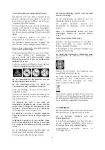
Lower  drum  to  securely  hold  straight‐edge  in 
place. See Figure 6‐4. Raise infeed/outfeed table 
until table surface is slightly below conveyor belt 
surface. Tighten screws on that side. 

8.


Reposition  straight‐edge  to  other  side  of  table 
and repeat. 

9.


Loosen  screw  (HP6)  and  rotate  eccentric  cam 
(HP8) until it contacts lip of table bracket. Do this 
on both sides of infeed table. This ensures infeed 
table  will  remain  level  with  conveyor  table  each 
time it is returned to operating position. Tighten 
screws (HP6).  

If stock being sanded is bowed, warped or otherwise 
inconsistent,  be  sure  tables  are  lower  than  top  of 
conveyor table. 

If  stock  slips  on  conveyor,  the  tables  may  be 
positioned  too  high.  Lower  tables  to  allow  stock  to 
remain in contact with conveyor. 


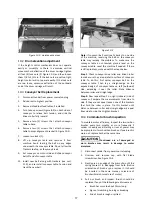
Figure 6‐4:  extension table alignment 
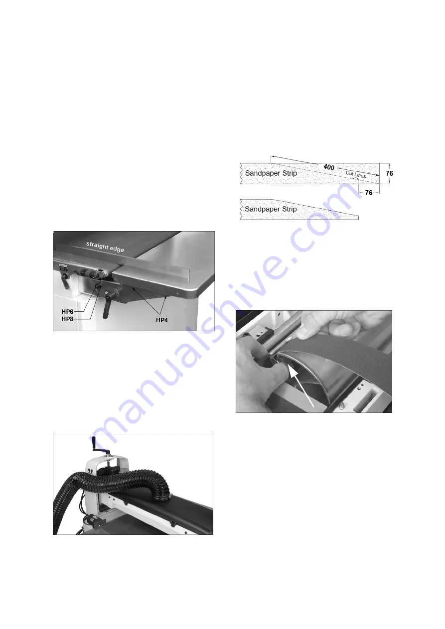
 

6.7

 Dust collection 

Dust  collection  is  mandatory  for  a  safe  work 
environment and extended abrasive life. The machine 
is  equipped  with  a  100mm  dust  collection  port. 
Secure a 100mm dust collection hose to the port with 
a  hose  clamp  (Figure  6‐5),  and  connect  to  a  dust 
collector (minimum 560m

3

/h). 


Figure 6‐5  (hose and clamp not included) 
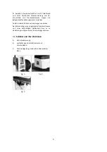
6.8

  Installing abrasives 

Proper  attachment  of  the  abrasive  strip  to  the  drum 
is  critical  to  achieving  top  performance  from  your 
drum sander.  

An  80‐grit,  76mm  wide  abrasive  strip  is  pre‐installed 
on the drum.  

(TIP: If you are using an after‐market abrasive, use a 
new  JET‐supplied  abrasive  as  a  template  to  quickly 
cut a new strip.  


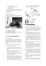
Figure 6‐6: abrasive trimming 

To install abrasive strip: 

1.


Press  fastener  lever  (Figure  6‐7)  on  outboard 
(left)  end  of  drum,  and  insert  tapered  end  of 
abrasive through slit in fastener, as shown. Insert 
approximately  75mm  of  abrasive  strip  into 
fastener.  Align  tapered  edge  of  abrasive  strip 
with left edge of drum.  


Figure 6‐7 

2.


Release fastener lever to secure end of strip. 

3.


Begin  wrapping  abrasive  around  drum.  The 
tapered edge of strip end should follow as close 
as possible to edge of drum. 

4.


Continue  to  wrap  abrasive  in  spiral  fashion  by 
rotating  drum  with  one  hand  and  guiding  strip 
with the other. See Figure 6‐8.  

Successive  windings  of  strip  must 

not  have  any 

overlap.

  They  should  be  flush  with  previous 

windings or with a slight gap between.  

Содержание JWDS-2244OSC-M

Страница 1: ...der Zylinderschleifmaschine Ponceuse cylindre oscillant Original GB Operating Instructions Translations D Gebrauchsanleitung F Mode d emploi TOOL FRANCE SARL 9 Rue des Pyr n es 91090 LISSES France www...

Страница 2: ...ctive Maschinenrichtlinie Directive Machines 2014 30 EU Electromagnetic compatibility elektromagnetische Vertr glichkeit compatibilit lectromagn tique 2011 65 EU RoHS directive RoHS Richtlinie Directi...

Страница 3: ...r assembly 8 6 3 Assembling stand 9 6 4 Mounting sander to stand 9 6 5 Handle and hose hanger 9 6 6 Infeed and outfeed tables optional accessory 9 6 7 Dust collection 10 6 8 Installing abrasives 10 7...

Страница 4: ...regulations you should observe the generally recognized technical rules concerning the operation of woodworking machines Any other use exceeds authorization In the event of unauthorized use of the ma...

Страница 5: ...ts until the machine is at a standstill Do not stand on the machine Connection and repair work on the electrical installation may be carried out by a qualified electrician only Have a damaged or worn...

Страница 6: ...dB in operation Acoustic pressure level LpA EN ISO 11202 Capacities Maximum board width single pass 560 mm Maximum board width two passes 1120 mm Maximum board thickness 102 mm Minimum board length 60...

Страница 7: ...mm Weights Net weight 98 kg Shipping weight 131 kg The specifications in this manual were current at time of publication but because of our policy of continuous improvement JET reserves the right to...

Страница 8: ...manual thoroughly for assembly maintenance and safety instructions 6 1 Shipping contents Box 1 see Figure 6 1 1 Sander with conveyor table A 1 Height adjust handle B 1 Hose hanger C 2 Socket head scre...

Страница 9: ...th screws and washers C1 C2 6 6 Infeed and outfeed tables optional accessory The sander must be bolted to the stand or a work table when using these table extensions Maximum working load of each table...

Страница 10: ...the port with a hose clamp Figure 6 5 and connect to a dust collector minimum 560m3 h Figure 6 5 hose and clamp not included 6 8 Installing abrasives Proper attachment of the abrasive strip to the dru...

Страница 11: ...ons 8 0 Adjustments Disconnect sander from power source before making adjustments 8 1 Drum Height Control Drum height and depth of cut are controlled by height adjustment handle see Figure 5 1 Rotatin...

Страница 12: ...sion If tension is affected if may become necessary to use both take up screws to accomplish tensioning and tracking 8 4 3 Trackers The sander comes equipped with Trackers ceramic guides that reduce t...

Страница 13: ...tment as the sander receives use Improperly adjusted tension rollers i e those set too high rendering them non functional could allow kickback of pieces being sanded You can increase or decrease tensi...

Страница 14: ...r or backer board not provided is recommended for cuts 1 5mm or less This is a flat board usually of wood or MDF slightly larger than the workpiece and of even thickness placed beneath the workpiece a...

Страница 15: ...ks that will boost return on your investment For example it will speed up fine sanding work often done with slower dust generating hand sanders and will achieve fine thickness adjustments not possible...

Страница 16: ...ock removal The optimum feeding angle for stock removal is about 60 Angling the workpiece for stock removal provides other advantages such as less loading of certain areas of the drum due to glue line...

Страница 17: ...ot twisted place a level on the conveyor table Level the machine if needed If there is still a problem proceed with the steps below Step 1 Check conveyor drive roller and driven roller to make sure th...

Страница 18: ...ker is magnetized and will stick to side wall of conveyor table Do not install tracker if edge of conveyor belt is damaged or torn Figure 11 1 Underside of conveyor shown 7 With first tracker installe...

Страница 19: ...glossy surface which will not accept stains evenly This will vary by type of wood Oak for example is susceptible to burnishing because of its open pores 12 2 Cleaning abrasive strips Regularly clean t...

Страница 20: ...orrect fuse or circuit breaker Loud repetitive noise or vibration coming from machine Fasteners loose Inspect fasteners and tighten where needed Motor fan is hitting cover Tighten fan or shim fan cove...

Страница 21: ...pples in sanded surface A Non uniformly spaced ripples B Uniformly spaced ripples A Uneven feed rate Conveyor belt slipping see above Board slips on conveyor belt see above Conveyor motor stalls see a...

Страница 22: ...n tigte Werkzeuge 8 6 3 Montage des Gestells 9 6 4 Die Schleifmaschine auf dem Gestell anbringen 9 6 5 Montage von Kurbel und Schlauchst tze 9 6 6 Montage der Verl ngerungstische optionales Zubeh r 9...

Страница 23: ...funktionst chtig und korrekt montiert sein Zus tzlich zu den in dieser Betriebsanleitung aufgef hrten Sicherheitsma nahmen und den in Ihrem Land geltenden Regelungen m ssen au erdem die allgemein ane...

Страница 24: ...werden und darf keinem Regen ausgesetzt werden Schleifstaub ist explosiv und kann dar ber hinaus auch ein Gesundheitsrisiko darstellen Es muss stets eine geeignete Staubabsaugvorrichtung verwendet wer...

Страница 25: ...nden Defekte Schleifmittel k nnen Verletzungen verursachen Bei Verwendung eines ungeeigneten Netzanschlusses und eines besch digten Netzkabels kann es zu Verletzungen aufgrund eines Stromschlags komme...

Страница 26: ...rte Maximale Plattenbreite ein Durchlauf 560 mm Maximale Plattenbreite zwei Durchl ufe 1120 mm Maximale Plattenst rke 102 mm Kleinste Plattenl nge 60 mm Kleinste Plattenst rke 3 0 8 mm Werkstoffe Unte...

Страница 27: ...131 kg Die technischen Daten in diesem Handbuch waren zum Zeitpunkt der Ver ffentlichung aktuell Aufgrund unserer Politik fortw hrender Verbesserung beh lt sich JET das Recht vor technische Daten jed...

Страница 28: ...e Bedienungsanleitung zwecks Verinnerlichung von Montage und Wartungsvorg ngen sowie Sicherheitsanweisungen sorgf ltig durchlesen 6 1 Lieferumfang Haupteinheit siehe Abb 6 1 1 Schleifmaschine mit Vors...

Страница 29: ...und Vorschubband entfernen 3 Die Schlauchablage mit 2 Schrauben und Scheiben C1 C2 am Geh use befestigen 6 6 Verl ngerungstische optionales Zubeh r Zur sicheren Verwendung der Verl ngerungstische muss...

Страница 30: ...bung und eine gute Lebensdauer der Schleifmittel unbedingt erforderlich Die Maschine ist mit einem 100mm Absaugstutzen versehen Den Absaugschlauch mit einer Schlauchschelle Abb 6 5 befestigen und an e...

Страница 31: ...ng vor den angef hrten Empfehlungen 8 0 Einstellungen Vor der Ausf hrung von Einstell oder Wartungsarbeiten die Maschine vom Stromnetz trennen Netzstecker ziehen 8 1 H heneinstellung der Trommel Tromm...

Страница 32: ...hraube an dieser Seite anziehen Hinweis Die Einstellschraube immer nur um jeweils 1 4 Drehung verstellen nicht mehr Abwarten wie das Vorschubband darauf reagiert Erst dann fortfahren Gr bere Einstellv...

Страница 33: ...druckrollen sind federbelastet damit Druck auf das Werkst ck ausge bt wird und Rutschbewegungen vermieden werden Der Federdruck ist ab Werk voreingestellt er kann bei Bedarf verstellt werden Auf der T...

Страница 34: ...sse anzueignen und sich mit der Maschine vertraut zu machen HINWEIS F r Schleifgutst rken unter 1 5mm wird die Verwendung einer Zuf hrlade nicht mitgeliefert empfohlen Dies ist eine flache Platte norm...

Страница 35: ...ifstaubaufkommen ausgef hrt werden Diese Schleifmaschine kann zur Oberfl chenbearbeitung von figurierten H lzern z B Vogelaugenahorn oder Riegelahorn verwendet werden ohne dass Oberfl chensch den veru...

Страница 36: ...ef hrt werden Jedoch schon ein kleiner Schleifgutversatzwinkel f hrt zu einem effizienteren Materialabtrag Der optimale Schleifgutzuf hrwinkel betr gt ca 60 Das Anwinkeln des Werkst cks bietet weitere...

Страница 37: ...chine hin kann ein Seitentausch des Vorschubbandes dieses Problem beheben berpr fen Sie mit einer Wasserwaage ob der Vorschubtisch uneben verschr nkt ist falls ja das Maschinengestell neu nivellieren...

Страница 38: ...Seitenwand des Vorschubtisches Abb 11 1 Unterseite der F rdereinheit 4 Bei korrekt installierter Nachf hreinrichtung l uft das Vorschubband gerade durch den F hrungsschlitz Hinweis Der zweite F hrungs...

Страница 39: ...F llen k nnen stark zugesetzte Bereiche mit auf Kante gehaltenem Plexiglas entfernt werden Beim Reinigen von Schleifband stets einen Augen und Staubschutz tragen Vorsichtig vorgehen zur Vermeidung de...

Страница 40: ...rzschluss im Motor oder gelockerte Verbindungen Anschl sse Verbindungen Anschl sse am Motor auf gelockerte oder kurzgeschlossene Klemmen oder abgenutzte Isolierung berpr fen Spannung zu niedrig Spannu...

Страница 41: ...hwindigkeit erh hen Schleifmittel ist abgenutzt Schleifmittel austauschen Werkst ck rutscht auf dem Vorschubband Andruckrollen Druck zu niedrig Rollenandruck erh hen Vorschubgeschwindigkeit zu hoch Vo...

Страница 42: ...pport tuyau 7 6 6 Tables d entr e et de sortie accessoire en option 8 6 7 Collecte des poussi res 9 6 8 Installation des abrasifs 9 7 0 Connexions lectriques 10 8 0 R glages 10 8 1 Contr le de la haut...

Страница 43: ...icables votre pays Toute autre utilisation est strictement interdite En cas d usage non autoris le fabricant renonce toute responsabilit qui est transf r e l op rateur 3 2 Consignes de s curit g n ral...

Страница 44: ...e n est pas mise l arr t Ne vous tenez pas sur la machine Les travaux de r paration et de connexion sur l installation lectrique doivent tre uniquement effectu s par un lectricien qualifi Remplacez im...

Страница 45: ...coustique LpA EN ISO 11202 Capacit s Largeur maximum de la plaque un seul passage 560 mm Largeur maximum de la plaque deux passages 1120 mm Epaisseur maximum de la plaque 102 mm Longueur minimum de la...

Страница 46: ...320 mm Poids Poids net 98 kg Poids d exp dition 131 kg Les sp cifications de ce manuel entrent en vigueur au moment de la publication mais en raison de notre politique d am lioration continue JET se r...

Страница 47: ...votre distributeur Lisez attentivement les instructions de montage d entretien et de s curit fournies dans ce manuel d instructions 6 1 Contenu d exp dition Bo te n 1 Voir la Figure 6 1 1 Ponceuse av...

Страница 48: ...le cylindre et le convoyeur 3 Installez le support tuyau C avec les vis et les rondelles C1 C2 6 6 Tables d entr e et de sortie accessoire en option La ponceuse doit tre boulonn e sur le support ou u...

Страница 49: ...our permettre au mat riau de rester en contact avec le convoyeur Figure 6 4 Alignement des extensions de table 6 7 Collecte des poussi res La collecte de poussi re est obligatoire pour un environnemen...

Страница 50: ...est raccord e un circuit prot g par des fusibles utilisez un fusible temporis marqu T Les codes locaux pr valent sur les recommandations 8 0 R glages D branchez la ponceuse de sa source d alimentation...

Страница 51: ...du convoyeur Si elle d rive serrez ou desserrez la vis de tension Remarque Tournez la vis de tension d 1 4 de tour seulement ce moment Laissez la courroie un temps de r action au r glage avant de cont...

Страница 52: ...inf rieur 560 mm retournez la table du convoyeur en position parall le Tournez le bouton en direction oppos e jusqu ce que le contre crou D soit touch Le contre crou fait but e pour le parall lisme d...

Страница 53: ...pe correcte entrer les variables de grains abrasifs le type de bois et la vitesse d avance Pour obtenir les meilleurs r sultats utilisez des bouts de bois pour vous entra ner au pon age et d velopper...

Страница 54: ...ue vous usinez commence montrer des traces de br lure Pour le cerisier l rable dur ou autres bois durs l utilisation d une profondeur moins profonde ou une vitesse d avance plus rapide peut aider mini...

Страница 55: ...le convoyeur lorsqu il va sur un rail du mat riau peut aider emp cher les sillons ou creux Cela permet l abrasif de poncer une largeur plus grande avec moins d efforts et d obtenir une meilleure unif...

Страница 56: ...d un c t de la machine inversez la bande sur la table du convoyeur pour rem dier ce probl me Pour vous assurer que la table du convoyeur n est pas tordue placez un niveau sur la table du convoyeur Me...

Страница 57: ...les 2 vis et desserrez les 2 vis oreilles maintenant la table du convoyeur la base de la ponceuse 5 Soulevez la table du convoyeur et faites la glisser hors de la ponceuse Tournez la table du convoye...

Страница 58: ...220 sont principalement des grains de finition con us pour enlever les dessins de rayures des grains pr c demment utilis s Pour obtenir les meilleurs r sultats ne sautez jamais plus d une grosseur de...

Страница 59: ...nte Nettoyez le ventilateur du moteur avec de l air comprim pour r tablir une circulation d air normale Moteur surcharg SandSmartTM ne fonctionne pas correctement V rifiez et r parez les commandes Le...

Страница 60: ...gmentez la vitesse d avance L abrasif est us Remplacez l abrasif La plaque glisse de la courroie transporteuse Tension des rouleaux trop lev e Abaissez la tension des rouleaux Vitesse d avance excessi...

Страница 61: ...21 This page is intentionally blank...

Страница 62: ...22 This page is intentionally blank...

Страница 63: ...TOOL FRANCE SARL 9 Rue des Pyr n es 91090 LISSES France...

Отзывы: